


All installations and services must be performed by qualified service personnel.
16
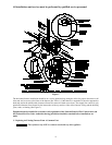
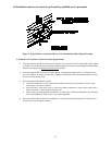
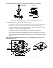
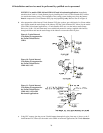
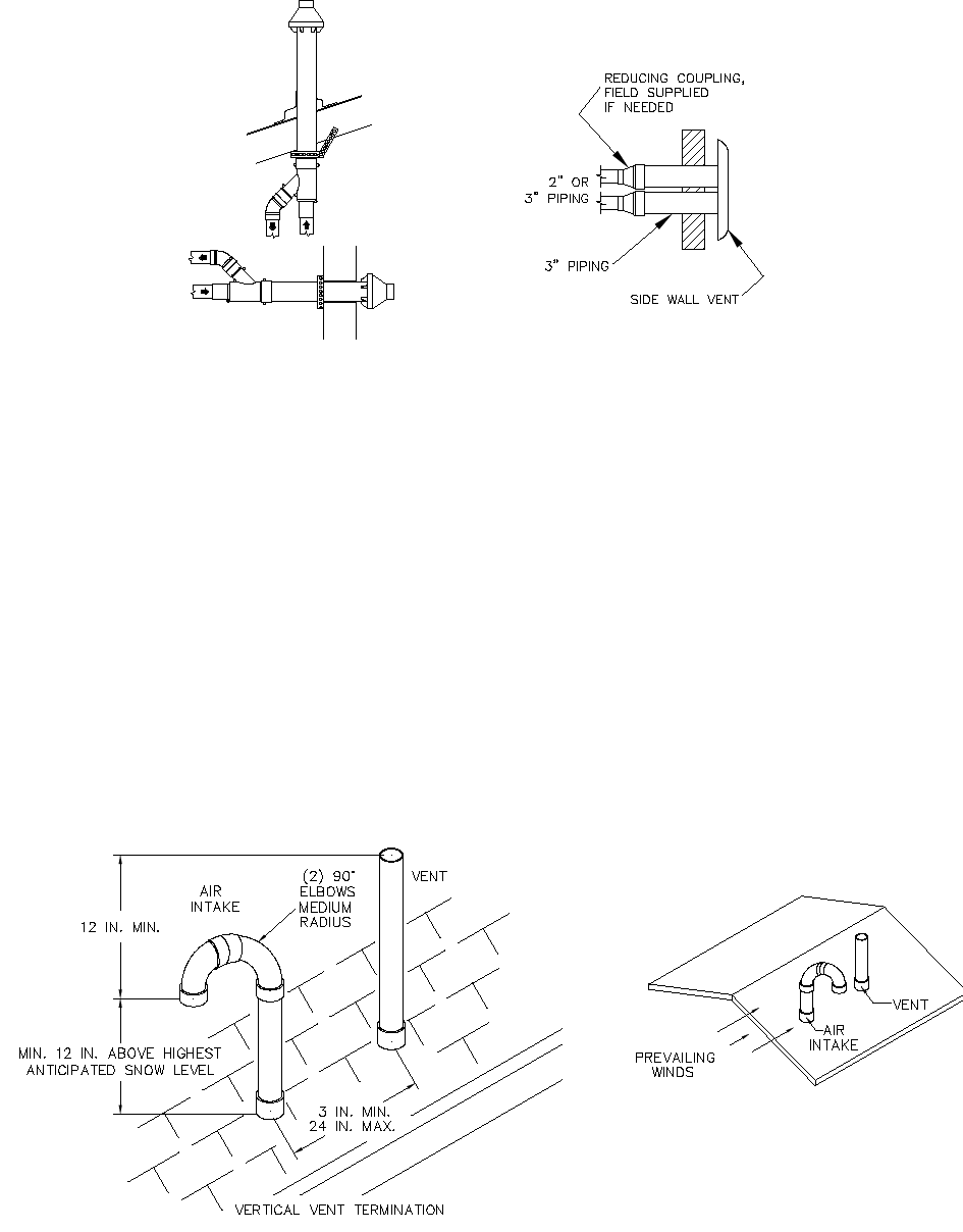
Figure 6: Optional Direct Vent Kits for the CHB1 / CDB1 Model Series of Furnaces
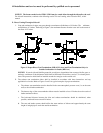
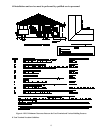
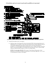
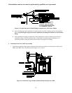
G. Connecting The Furnace To Roof Exhaust / Intake Terminations
If it is not desirable, or feasible, to vent the furnace through a sidewall, it may be vertically vented through the
roof. Installation shall conform to the following guidelines, which are illustrated in Figure 6A, below.
1. The outlet of the exhaust vent and the inlet of the combustion air intake, i.e. the terminations, shall be a
minimum of 12-inches above highest anticipated snow level.
2. The exhaust vent outlet must be installed a minimum of 12-inches above the air intake inlet.
3. Where exposed to prevailing winds, the combustion air intake shall be installed upwind of the vent outlet.
4. The exhaust vent and combustion air intake shall be a minimum of 3-inches and a maximum of 24 inches
apart.
NOTICE: When the vent termination is installed correctly, a draft should NOT be present in the system
during the furnace off-cycle.
Figure 6A: Typical Rooftop Vent and Air Intake Termination Construction Details
370191
SIDE WALL VENT KIT
VERTICAL
HORIZONTAL
AOPS7488 / AOPS7489
CONENTRIC VENT KIT