


All installations and services must be performed by qualified service personnel.
21
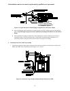
PVC tee). Couple the drain tee assembly to the pre-cut 2-inch diameter PVC pipe using the reinforced
rubber hose and the two (2) band clamps supplied.
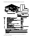
NOTICE: All PVC thermoplastic pipe must be supported beginning directly over the exhaust
vent tee assembly, then every 4-feet thereafter, and at every joint. Trial fit the entire exhaust vent
and air intake piping systems, making sure the slope and length of the piping are correct, before
permanently assembling the pipe components.
If the vent piping is run through an unconditioned space, it must be insulated with 1-inch thick
foil-faced fiberglass insulation, or an equivalent product.
3. Connecting The Combustion Air Intake Piping
: Outside combustion air must NOT be drawn from an area directly adjacent to a pool, hot
tub or spa. Measures should be taken to prevent the entry of corrosive chemicals or vapors into the
combustion air supply. Such chemicals include, but are not limited to, chlorinated and/or fluorinated
hydrocarbons such as found in refrigerants, aerosol propellants, dry cleaning fluids, degreasers and
removers. Other harmful compounds may come from bleaches, air fresheners or mastics. Vapors from
such products can form reactive acid producing chemical species when burned in a gas flame. Should
acidic compounds form in the furnace they may significantly reduce the useful life of the furnace.
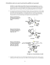
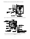
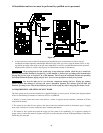
a. For the models CHB1–50 / –75 and CDB1–50 / –75, install a 2-inch PVC elbow with sleeve and
coupling (for models CHB1–100 / –125 and CDB1–100 & –125, a 3-inch PVC elbow with sleeve) on
the inlet of the burner box. Measure the length of pipe needed to clear the casing. Be sure to allow
sufficient length to account for insertion of the pipe into the elbow at the burner box and the elbow, or
coupling fitting, on the end. Cut the pipe to length.
b. After preparation of the thermoplastic pipe, drive one (1) #8 x 3/4 inch sheet metal screw with black
protective coating (supplied with furnace) through the PVC coupling, or sleeve, into the metal collar of
the burner box to secure the piping in place.
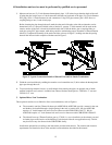
NOTICE: DO NOT apply silicone rubber type sealant or PVC cement to the joint at the
thermoplastic piping connection to the metal burner box collar. Attach the PVC elbow to the
sleeve and then to the coupling where required, using silicone rubber type sealant, refer to
Figure 12.
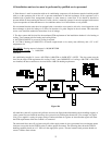
c. Insert the precut 2-inch (or 3-inch) thermoplastic pipe into the elbow at the burner box and to the
elbow, or coupler, just outside the furnace using a silicone rubber type sealant. To properly make these
seals, run a thin bead of silicone type sealant around the circumference of the PVC pipe, about 3/8 inch
from either end. Insert the straight pipe section into the appropriate couplings and elbows and rotate 1/4
turn. Silicone rubber type sealants remain pliable after the initial setup period has passed allowing for
relatively easy disconnection of the air intake system, should the burner assembly require removal at a
later date, refer to Figure 12.
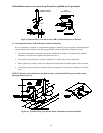
NOTICE: When applying silicone sealants, ensure that no excess sealant is pushed into the inside
opening of the pipe. This may cause flow restriction within the piping. If possible, always apply
the sealant to the male component of the piping joint.