


NOTE: DIAGRAMS & ILLUSTRATION NOT TO SCALE.
9
Step 2. Align the canopy with the holes in the
top frame.
Step 3. Replace the screws previously removed.
Step 4. Tighten side screws. Make sure the
canopy is level and secure.
OPTIONAL EQUIPMENT
Blower Kit
Circulating Models Only
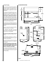
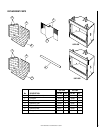
If you are installing one of the blower kits,
Models FBK-100 or FBK 200, follow Steps 1
through 5, and see the installation instructions
provided with the kit for electrical wiring re-
quirements (
see Figure 11 )
. The firebox must
be connected to main power supply at time of
installation if a forced air kit is to be installed
later. The electrical connections must be made
before the firebox is framed and enclosed in the
finished walls.
This appliance must be electrically grounded in
accordance with local codes or, in the absence
of local codes, the national electrical code,
ANSI/NFPA 70 - (Latest Edition).
CAUTION: ELECTRICAL CONNECTIONS
SHOULD ONLY BE PERFORMED BY A QUALI-
FIED, LICENSED ELECTRICIAN. MAIN POWER
MUST BE OFF WHEN CONNECTING TO MAIN
ELECTRICAL POWER SUPPLY OR PERFORM-
ING SERVICE.
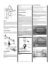
Note: The nailing flange and the area directly
behind the nailing flange is exempt from the
clearances described on the firebox clearance
label.
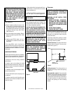
Step 5. To safely operate the heater with con-
sideration of the mantel clearances the canopy
must be installed.
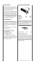
Canopy Installation
The factory-supplied canopy must be installed
on the firebox for safe operation. See
Figure 10
.
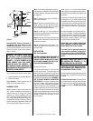
8d Nail
Figure 9
Grounded
to Appliance
Blower Motor
Motor Plug
Receptacle
120V
Appliance Junction Box
NOTE: If any of the original wire as supplied
must be replaced, it must be replaced with type
AWM 105°c – 18Ga. wire
Figure 11
Figure 10
Attaching
Screws
UVF-500
Shown
UVF-500
Canopies
Firebox
Opening
UVF-600
Canopies
3 Screws for 500 Models
4 Screws for 600 Models
Firebox
Opening
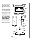
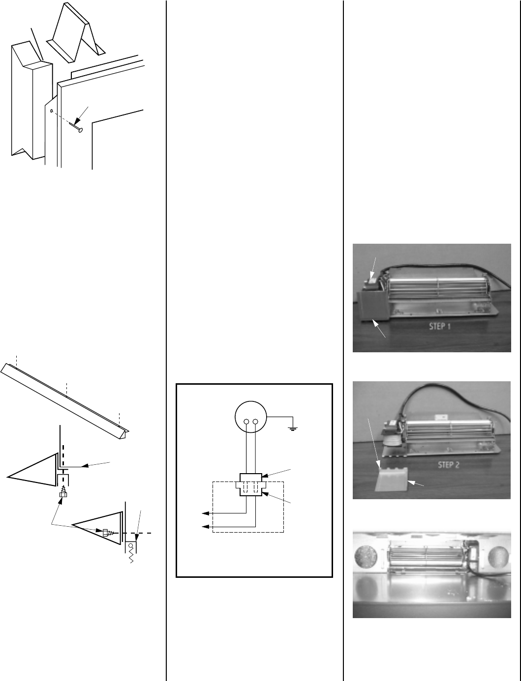
Blower Kit Installation
To install the blower kit, follow Steps 1 thru 5
and refer to
Figures 12, 13 and 14
.
Step 1. Locate the blower motor shield.
Step 2. Remove the motor shield by bending it
along the perforation until the tabs break away.
Step 3. With the motor shield removed, place
the blower in the unit with the power cord up
and slide to the back of the unit until the motor
is behind the rear support.
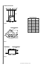
Step 4. Rotate the blower 90 degrees, so that
the discharge is up.
Step 5. Move left side of blower around until it
is in the proper position and bend the retaining
tabs in the bottom of the unit up into the slots
on the blower.
Figure 12
Figure 13
Blower Motor
Motor Shield
Perforation
Tabs
Motor Shield Removed
Step 1. Remove the screws from the top front
frame assembly. There are three (3) screws on
the 500 models and four (4) screws on the 600
models.
Figure 14
Rotated Blower In Final Position