


NOTE: DIAGRAMS & ILLUSTRATION NOT TO SCALE.
7
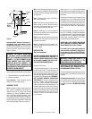
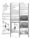
Firebox Installation
Note: The firebox must be installed giving full
consideration to the clearance and height re-
quirements identified in this manual.
Step 1. Slide the firebox into prepared framing
or position firebox in its final position and
frame later.
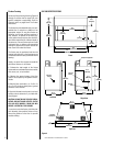
Step 2. Refer to firebox and framing specifica-
tions on pages 6, 7and 8
Figures 6 through 10
for framing
dimensions and details. Framing
header may be positioned directly on the fire-
box top spacers.
Note: The framed depth from a framed wall,
must always be measured from a finished
surface. If a wall covering such as drywall is to
be attached to the rear wall, then the depth
must be measured from the drywall surface. It
is important that this dimension be exact.
IMPORTANT: UNDER NO CIRCUMSTANCES
SHALL THE FIREBOX TOP SPACERS BE RE-
MOVED OR MODIFIED. THE HEADER MAY BE
IN DIRECT CONTACT WITH THE TOP SPAC-
ERS BUT MUST NOT BE SUPPORTED BY THEM
OR NOTCHED TO FIT AROUND THEM.
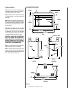
Step 3. Level the firebox by checking the top
edge of the firebox. Shim if necessary.
Step 4. Fireplace should be secured to side
framing members using the full length nailing
tabs at the top and bottom of the fireplace front
face. Use 8d nails (
see Figure 9
).
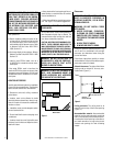
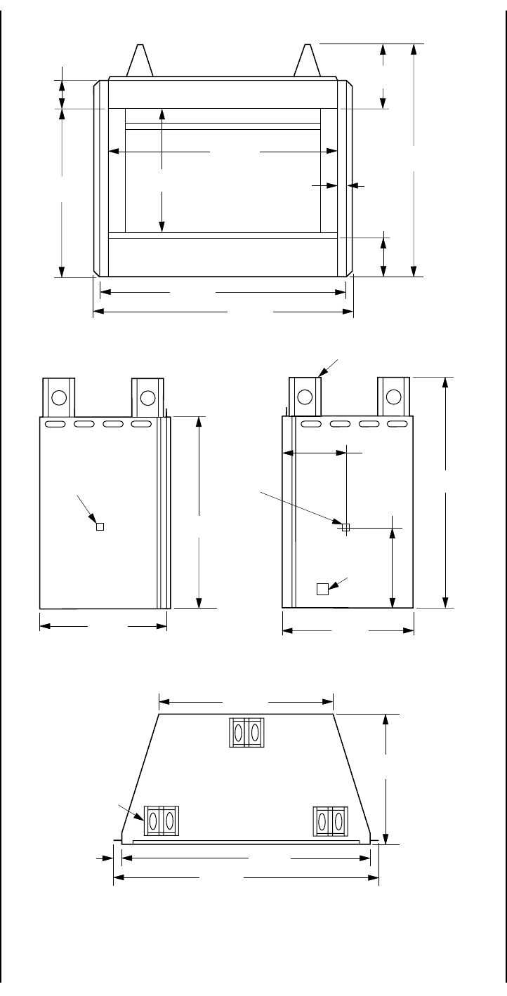
Figure 5
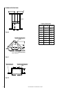
UVF-600 SPECIFICATIONS
45"
(1143 mm)
31 ⁹⁄₁₆"
(802 mm)
21 ¹⁄₄"
(540 mm)
Top View
Right Side
Gas Line
Access
Junction
Box
9 ⁷⁄₈"
(251 mm)
43"
(1092 mm)
21 ¹⁄₄"
(540 mm)
20 ⁵⁄₈"
(524 mm)
Left Side
45"
(1143 mm)
Front
43"
(1092 mm)
7 ³⁄₁₆"
(183 mm)
41"
(1041 mm)
2"
(51 mm)
22 ⁵⁄₁₆"
(566 mm)
13 ³⁄₈"
(340 mm)
8 ³⁄₈"
(213 mm)
Fireplace Top Spacer
Fireplace
Top Spacer
Gas Line
Access
10"
(254 mm)
47"
(1194 mm)
1"
(25 mm)
38"
(965 mm)
47"
(1194 mm)
29 ⁵⁄₈"
(752 mm)