


NOTE: DIAGRAMS & ILLUSTRATION NOT TO SCALE.
5
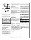
Install only a ¹⁄₂" (1 ¹⁄₂" max.) inside diameter
approved gas line through the firebox wall for
connection to the unvented room heater inside
the firebox.
Ensure that a sediment trap is installed in the
existing gas line, if not, install a sediment trap
upstream of the heater to prevent moisture and
contaminants from passing through trap to the
heater controls and burners. Failure to do so
could prevent the heater from operating reli-
ably.
An external regulator must be used on all pro-
pane (L.P.G.) heaters, in addition to the regula-
tor fitted to the heater, to reduce the supply tank
pressure to 13" w.c. (maximum). Any copper
tubing used to supply propane (L.P.G.) from
the tank must be internally tinned.
IMPORTANT: HOLD HEATER REGULATOR
WITH A WRENCH TO PREVENT MOVEMENT
WHEN CONNECTING TO INLET PIPING.
Check Gas Type: The gas supply must be the
same as stated on the heater’s rating plate. If
the gas supply is different, DO NOT INSTALL
the heater. Contact your dealer for the correct
model.
WARNING: CONNECTING DIRECTLY TO
AN UNREGULATED PROPANE (L.P.G.)
TANK CAN CAUSE AN EXPLOSION.
IMPORTANT: RE-PACK INSULATION MATE-
RIAL IN SQUARE HOLE AROUND GAS LINE,
INTERIOR AND EXTERIOR, TO SEAL.
Consult installation and operating instructions
for the model of unvented room heater to be
installed.
Checking Gas Connections: Test all gas joints
from the gas meter to the gas heater regulator
for leaks using soap and water solution after
completing connection. DO NOT USE AN OPEN
FLAME.
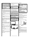
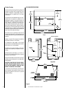
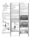
WARNING: THE CANOPY HOOD MUST
BE IN PLACE TO BE IN COMPLIANCE
WITH THE CLEARANCES SPECIFIED IN
FIGURE 3
. DO NOT REMOVE OR RE-
PLACE CANOPY, ONLY USE CANOPY
SUPPLIED WITH THE FIREBOX. DO
NOT USE ANY CANOPY WHICH MAY BE
PROVIDED WITH THE DECORATIVE TYPE
UNVENTED ROOM HEATER.
If your mantel profile is unsafe, you may either:
• Raise the mantel to an acceptable height, or
• Remove the mantel.
Floor clearance: These fireplaces may sit
directly on a combustible surface.
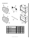
ASSEMBLY STEPS
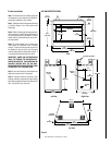
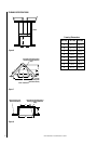
Note: Illustrations shown in this manual re-
flect “typical” installations with nominal di-
mensions and are for design and framing
reference only. Actual installations may vary
due to individual design preferences. How-
ever, always maintain minimum clearances to
combustible materials and do not violate any
specific installation requirements. Refer to the
Framing Specifications Figures on page 8.
Figure 3
Noncombustible material (minimum re-
quirements) with wood mantel or other
combustible projections: To install the fire-
box with a wood mantel, shelf or other com-
bustible projection above firebox opening.
Refer to
Figure 3
.
Note: The following steps represent the nor-
mal sequence of installation. Each installation
is unique, however, and might require a differ-
ent sequence.
Step 1. Position firebox prior to framing or
into prepared framing.
Step 2. Field wire main power supply to circu-
lating models for fan kit. (Electrical connec-
tions should only be performed by an experi-
enced, licensed/certified tradesman.)
Step 3. Plumb gas line. (Gas connections
should only be performed by an experienced,
licensed/certified tradesman.)
Step 4. Install decorative type unvented room
heater per the instructions provided with the
unvented room heater.
Step 5. Complete finish wall material, sur-
round and optional hearth extension to your
individual taste.
INSTALLATION
Gas Line Installation
CAUTION: PLUMBING CONNECTIONS SHOULD
ONLY BE PERFORMED BY A QUALIFIED, LI-
CENSED PLUMBER. MAIN GAS SUPPLY MUST
BE OFF WHEN PLUMBING GAS LINE TO FIRE-
PLACE OR PERFORMING SERVICE.
Consult all local codes.
It is recommended that the ¹⁄₂" gas line enter
the side of the firebox. Connect the gas line
before the firebox is enclosed in the finished
wall. The gas knockout is determined by an
indentation located at the bottom and slightly
off center in the side refractories. THE KNOCK-
OUT IS ALWAYS REMOVED FROM INSIDE
THE FIREBOX. If removal is attempted from
the outer wrapper, side-refractory damage
may occur. With a medium-sized hammer,
lightly tap the surface of the indentation. The
refractory material is very thin in this area and
is easily removed. Once a small hole has been
made, continue tapping until you have reached
sufficient diameter for the gas line to fit
through. The entire knockout does not have
to be removed.
18"
Min.
9"
Min.
Fireplace
Opening
Spacer
Combustible
Mantel
and Trim
8"
Max.
3"
Finished
Wall
Header
Canopy
Safe
Zone