


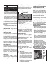
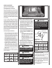

Clean Lower Control Compartment
Keep lower control compartment clean by
vacuuming or brushing it out at least twice a
year (also clean the air venturi with a brush or
wire). More frequent cleaning may be required
due to accumulation of lint from carpeting,
bedding materials, pet hair, spider webs, etc.
It
is very important that control compartments,
burners, circulating air passageways and air
venturi on the appliance are NOT obstructed
in any way.
Cleaning Glass
(see Front Glass Enclosure Panel, Removal and
Installation on Pages 7 & 8) Note: Clean glass
after first two weeks of operation (after Burn-In
period is over) and then only when necessary
and when the fireplace is cool. Wipe surface
with clean, dampened, soft cloth. Follow with
dry, soft towel as desired. Take care not to
scratch the glass surface.
The viewing glass should be cleaned periodi-
cally to remove any build-up caused from the
following (on next page):
Before re-lighting the fireplace, refer to the
lighting instructions in this manual. Instruc-
tions are also found on pull-out panels
located below the glass door in the control
compartment.
WARNING
Turn off gas and electrical power
before servicing the appliance.
CAUTION
Wear gloves and safety Glasses
for protection while doing
required maintenance.
IMPORTANT
Always verify proper operation
after servicing.
NOTE: DIAGRAMS & ILLUSTRATIONS ARE NOT TO SCALE.
5
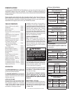
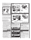
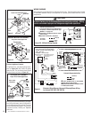
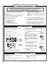
Figure 3
Honeywell Electronic Gas Valve
F
F
O
N
I
P
S
I
NO
L
O
R
T
N
O
C
G
I
N
T
I
ER
Manifold Pressure
Port
ON / OFF Switch
Inlet
Pressure
Port
Electronic Gas
Control Valve
Electronic Appliances -To light electronic appli-
ances refer to the detailed lighting instructions
found on Pages 18 & 19 of these instructions.
Electronic appliance lighting instructions may
also be found on the pull out lighting instruction
labels attached to the gas control valve.
If your electronic appliance is equipped with an
optional remote wall switch or remote control kit
the appliance main burner may be turned on and
off with the wall switch or remote control.
If your electronic appliance is not equipped
with a wall switch or remote control, the main
burner must be turned off and on with the gas
control switch. Toggle the switch from ON to
OFF to operate the main burner .
Variable Flame Height Adjustment
(Millivolt Appliances only)
1. All Millivolt appliances are equipped with a
variable gas control valve. Flame height for
these models may be adjusted through a
range between fixed low and high settings
while the appliance is in operation. Adjust
the flame height as desired after lighting the
appliance by rotating the variable adjustment
control knob (HI/LO) located on the front of
the valve (refer to Figures 4 & 5
).
2. During the first initial burns of these appli
-
ances, there will be some odor emitted (see
Burn-In Period on Page 4).
3. Keep the lower control compartment clean
by vacuuming or brushing at least twice a
year. More frequent cleaning may be required
due to excessive lint from carpeting, bedding
materials, pet hair, etc.
It is very important
that the control compartments, burners
and circulating air passageways of the
appliance are kept clean.
4. Always turn off gas to the pilot (millivolt
appliances) and let the appliance cool down
before cleaning. Before re-lighting, refer
to the lighting instructions in this manual.
Lighting instructions may also be found
on the pull out lighting instruction labels
attached to the gas control valve.
5. Always keep the appliance area clear and
free from combustible materials, gasoline
and other flammable liquids.
6. Remember, Millivolt appliances have a continu-
ous burning pilot flame. Exercise caution when
using products with combustible vapors.
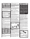
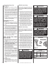
Honeywell Millivolt Gas Valve
Figure 5
O
N
O
F
F
P
I
L
O
T
L
O
H
I
OFF
ON
OFF
ON
Optional Blower OFF/ON
Rocker Switch
SIT Millivolt Gas Valve
Gas
Outlet
Gas
Inlet
Pilot Adjustment
Screw
Terminals
TPTH,TP & TH
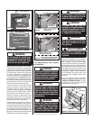
Figure 4
H
I
L
O
W
H
T
P
T
H
T
P
T
P
I
L
O
T
P
I
L
O
T
O
N
ti
O
F
F
IN
OUT
OFF
ON
OFF
ON
HI/LO Variable
Flame Height
Adjustment
Manifold Pressure Tap
Inlet Pressure Tap
Piezo Igniter
Main Gas
Control Knob
OFF/PILOT/ON
Piezo Igniter
Optional Burner OFF/ON
Rocker Switch
Piezo Igniter
Optional Blower OFF/ON
Rocker Switch
Optional Burner OFF/ON
Rocker Switch
HI/LO Variable
Flame Height
Adjustment
Main Gas
Control Knob
OFF/PILOT/ON
Manifold Pressure
Tap
Piezo Igniter
Inlet Pressure Tap
Gas
Outlet
Gas
Inlet
MAINTENANCE
(See Maintenance Schedule, Page 20)
Refer to the maintenance schedule for maintenance
tasks, procedures, periodicity and by whom they
should be performed. Always verify proper opera
-
tion of the appliance after servicing.