


12
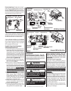
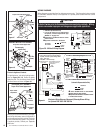
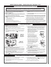
Electronic Appliance Checkout
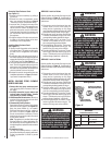
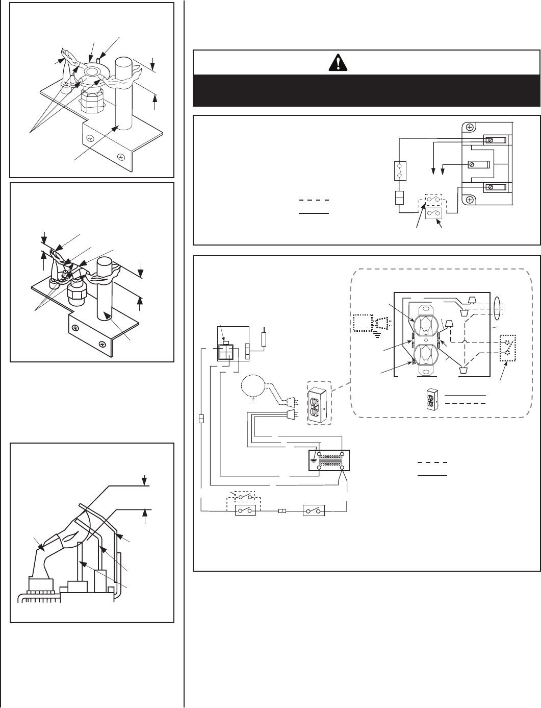
To light the burner, refer to the lighting instruc-
tions on Pages 18 & 19. Ensure the igniter
lights the pilot. The pilot flame should engulf
the flame sensor as shown in Figure 19.
With proper care and maintenance, your appli
-
ance will provide many years of enjoyment. If
you should experience any problem, first refer
to the troubleshooting guide in this manual.
If problem persists, contact your
Superior
distributor.
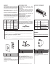
Figure 19
3/8" to 1/2"
(9 -13 mm)
Ground
Electrode
Flame Rod
Hot Surface
Igniter
Proper Flame
Adjustment
Pilot
Nozzels
ELECTRONIC PILOT ASSEMBLY
Proper Pilot Flame Appearance
Figure 17
Thermocouple
Thermopile
Pilot
Nozzels
SIT MILLIVOLT PILOT ASSEMBLY
3/8" Min.
(9 mm)
Igniter Rod
Hood
Proper Pilot Flame Appearance
Figure 18
Proper Pilot Flame Appearance
Thermocouple
Thermopile
Pilot
Nozzels
3/8" Min.
(9 mm)
1/8" Min.
(3 mm)
Igniter Rod
Hood
HONEYWELL MILLIVOLT PILOT ASSEMBLY
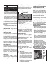
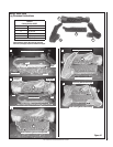
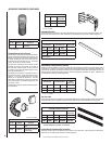
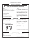
WIRING DIAGRAMS
Wiring diagrams are provided here for reference purposes only. This information is also provided
on schematics attached directly to the appliance on a pullout panel located within the control
compartment.
CAUTION
Label all wires prior to disconnection when servicing controls. Wiring
errors can cause improper and dangerous appliance operation.
• Schematic Representation Only
• If any of the original wire as supplied must
be replaced, it must be replaced with Type
AWM105 C - 18 gage wire.
u
Optional Kits - OFF/ON wall switch or remote
control receiver.
v
Appliance mounted OFF / ON Switch
Figure 20 - Millivolt Wiring Diagram
Field Wired
Factory
Wired
BK = BLACK
WT = WHITE
u v
NOTE: DIAGRAMS & ILLUSTRATIONS ARE NOT TO SCALE.
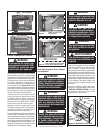
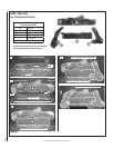
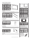
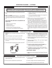
Figure 21
Electronic Wiring Diagram (Honeywell) Showing Blower Wiring
for Optional FBK-100 & FBK-200 Kits
1.
If any of the original wire as supplied must be
replaced, it must be replaced withType AWM
105°C - 18 GA. wire.
1.
2.
120V
, 60Hz – Less than 3 amps.
BK
T ransf.
120 V.
24 V
BL
Electronic Wiring Diagram (Honeywell)
R
BL
W
Gas Va lve
B
R
IGNITER
PILOT
ASSEMBLY
BK
BK BK
*ON/OFF Switch (Integral
with Gas Va lve )
*Leave the ON/OFF switch, which
is integral with the gas valve,
in the ON position.
SPILL SWITCH
(high limit disc)
WT
G
J-BOX
OPTIONAL
BLOWER
Field Wired
Factory
Wired
Schematic Representation Only
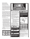
u Burner OFF/ON Switch on Valve Bracket
(optional switch on some models).
v Optional Control Switches - OFF/ON wall switch
or remote control receiver.
1. If any of the original wire as supplied must be replaced,
1. it must be replaced with Type AWM 105°C – 18 GA. wire.
2. 120V, 60Hz – Less than 3 amps.
Wiring Diagram
Showing the Blower Wiring
for the Optional FBK-100 Kit
Factory Wired
Field Wired
Schematic Representation Only
Junction Box
Tab Intact
Tab
Broken
Plug blower
into this
receptacle
n
e
erG
- dnuor
G
*Optional Accessory Switch
Optional
Blower
Ground
e
ti
h
W
-
lar
t
ueN
120 VAC - Black
Green
Ground
Screw
White
Green
Neutral
Side of
Receptacle
Hot
Side of
Receptacle
Red
Black
*J-BOX WIRING FOR
OPTIONAL (BLOWER
CONTROL) ACCESSORY
SWITCH
�
�
J-Box Wiring Diagram
u
v
TH
TP
TH
TP
WT
BK
BK
BK
Spill Switch