


NOTE: DIAGRAMS & ILLUSTRATIONS ARE NOT TO SCALE.
11
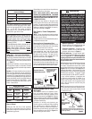
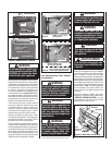
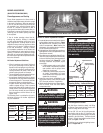
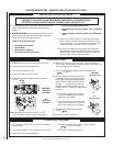
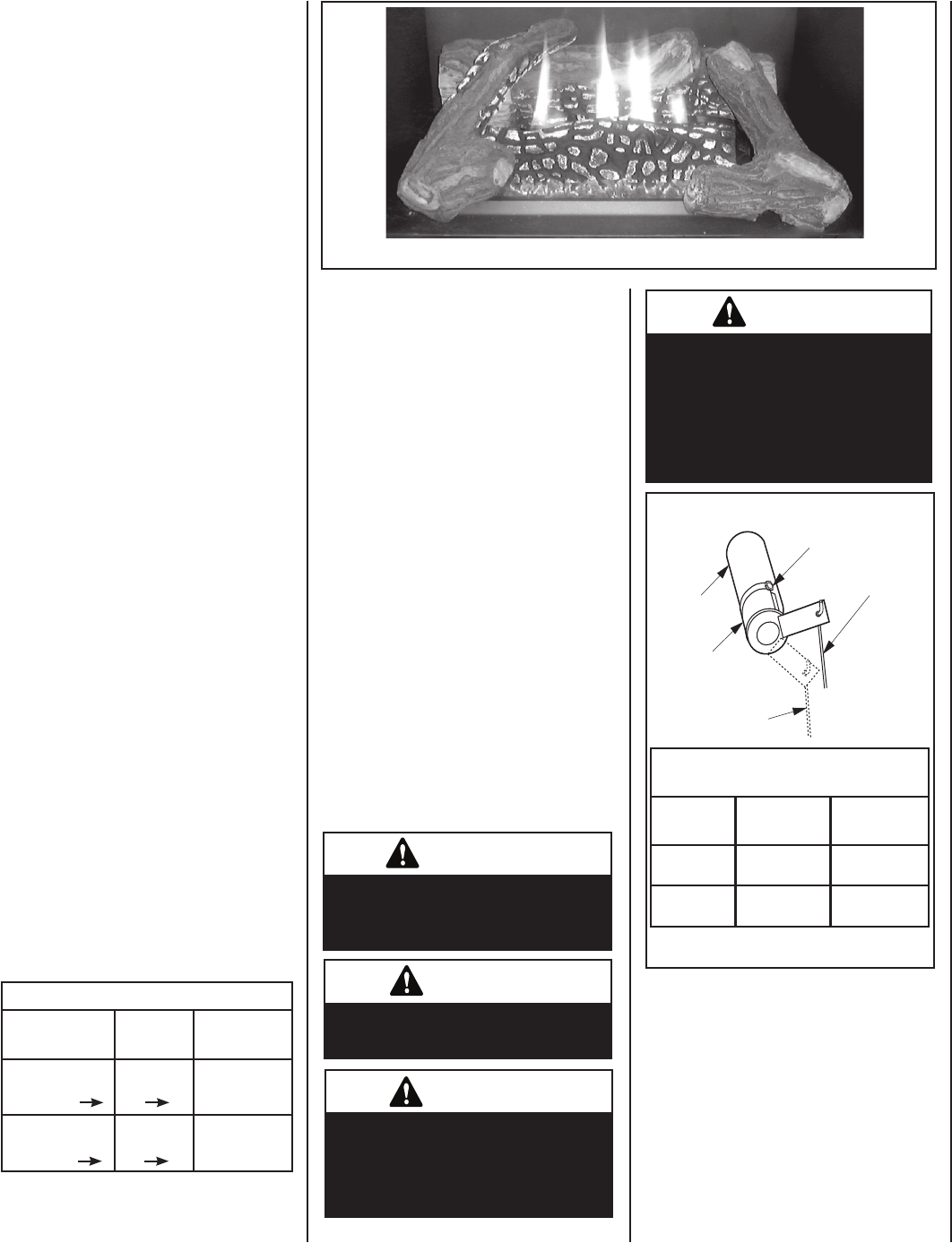
Figure 15 - Burner Flame Appearance Models SSBV-3530 & SSBV4035 Series
BURNER ADJUSTMENTS
(QUALIFIED TECHNICIANS ONLY)
Flame Appearance and Sooting
Proper flame appearance is a flame which is
blue at the base and becomes yellowish-orange
in the body of the flame. When the appliance
is first lit, the entire flame may be blue and
will gradually turn yellowish-orange during
the first 15 minutes of operation. If after a
short period the flame stays lowered blue, or
if the flame is orange with evidence of sooting
(black tip), the air shutter opening may need
to be adjusted.
If the air shutter openings closed too far,
sooting may develop. Sooting is indicated
by black puffs developing at the tips of very
long orange flames. Sooting results in black
deposits forming on the logs, appliance inside
surfaces and on exterior surfaces adjacent
to the vent termination. Sooting is caused
by incomplete combustion in the flames and
lack of combustion air entering the air shutter
opening. To achieve a warm yellowish-orange
flame with an orange body that does not soot,
the shutter opening must be adjusted between
these two extremes.
Air Shutter Adjustment Guidelines
• If there is smoke or soot present, first check
the log set positioning to ensure that the
flames are not impinging on any of the logs.
If the log set is properly positioned and a
sooting condition still exists, then the air
shutter opening should be increased.
• The more offsets in the vent system, the larger
the air shutter opening will need to be.
• An appliance operated with the air shutter
opened too far, may have flames that appear
blue and transparent. These weak, blue and
transparent flames are termed anemic.
• Propane models may exhibit flames which
candle or appear stringy. If this is present
and persists, adjust the air shutter to a more
closed position, then operate the appliance
for a few more minutes to ensure that the
flame normalizes and the flames do not
appear sooty.
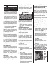
The following chart is provided to aid you in
achieving the correct air shutter adjustment
for your installation.
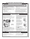
Air Shutter Adjustment Guidelines:
Amount of
Primary Air
Flame
Color
Air Shutter
Adjustment
If air shutter is
closed too far
Flame will
be orange
Air shutter
gap should be
increased
If air shutter is
open too far
Flame will
be blue
Air shutter
gap should be
decreased
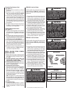
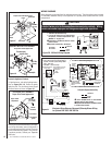
Figure 16
WARNING
Air shutter adjustment should
only be performed by a qualified
professional service technician.
WARNING
Ensure front glass panel is in place
and sealed during adjustment.
CAUTION
The air shutter door and nearby
appliance surfaces are hot. Exer-
cise caution to avoid injury while
adjusting flame appearance.
CAUTION
Carbon will be produced if the air
shutter is closed too much. Any
damage due to carboning result-
ing from improperly setting the
air shutter is not covered under
the warranty.
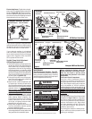
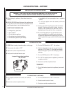
Burner Air Shutter Adjustment Procedure
1. Locate adjustment rod and adjust air shutter
to the standard setting as shown in Figure
16 (adjustment rod is located in the lower
control compartment). Note: Rotating the
adjustment rod counterclockwise increases
air and clockwise decreases air.
2. Light appliance (follow lighting procedure on
lighting label in control compartment or see
homeowners manual).
3. Allow the burner to operate for at least 15 min
-
utes while observing the flame continuously
to ensure that the proper flame appearance
has been achieved (see Figure 15
). If the
following conditions are present, adjust
accordingly.
• If flame appears weak or sooty, adjust
the air shutter, incrementally, to a more
open position until the proper flame
appearance is achieved.
• If flame stays lowered blue, adjust the
air shutter, incrementally, to a more
closed position until the proper flame
appearance is achieved.
4. Leave the control knob (off/pilot/on) in the
ON position and the burner OFF/ON switch
OFF (& remote switches, if applicable).
5.
When satisfied that the burner flame appear-
ance is normal, close the lower control
compartment door.
Burner Air Shutter Adjustment
Adjustment Rod Up
(Fully Open Position)
Air Shutter
Adjustment Rod Down
(minimum air opening
position)
Burner Tube
Adjustment Setscrew
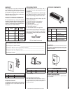
Millivolt Appliance Checkout
The pilot flame should be steady, not lifting
or floating. Flame should be blue in color with
traces of orange at the outer edge.
The top 3/8" (10 mm) at the pilot generator
(thermopile) and the top 1/8" minimum (tip)
of the quick drop out thermocouple should be
engulfed in the pilot flame. The flame should
project 1" (25 mm) beyond the hood at all three
ports. See
Figures17 or 18.
To light the burner, refer to the lighting instruc
-
tions on Pages 16 & 17.
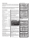
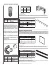
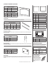
Main Burner Factory Air Shutter
Opening Setting - Inches (millimeter)
Model Natural
Gas
Propane
Gas
SSBV-3530
1/16"
(1.58 mm)
1/4"
(6.35 mm)
SSBV-4035
1/16"
(1.58 mm)
1/4"
(6.35 mm)