


7
System Installation
NOTE: All installation and maintenance are to be performed
only by qualified personnel who are familiar with local codes
and regulations, and experienced with this type of
equipment. CAUTION: Sharp edges and coil surfaces are
a potential injury hazard. Avoid contact with them.
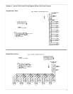
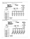
General
1. Structure supporting unit must be designed to support both
the unit and the fluid. Table 2 provides weight of fluid per
gallon. Tables 3 and 4 provide unit weight and volume
data. Provide suitable flashing of the roof, if this is a roof
installation. For ground level mounting, a concrete pad is
recommended. Mounting holes permit the unit to be bolted
down to withstand wind pressures. Provide adequate clear-
ance for unobstructed air flow to coils. See page 2 for
Space and Location requirements.
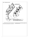
2. Level mounting is necessary to assure proper fluid distr-
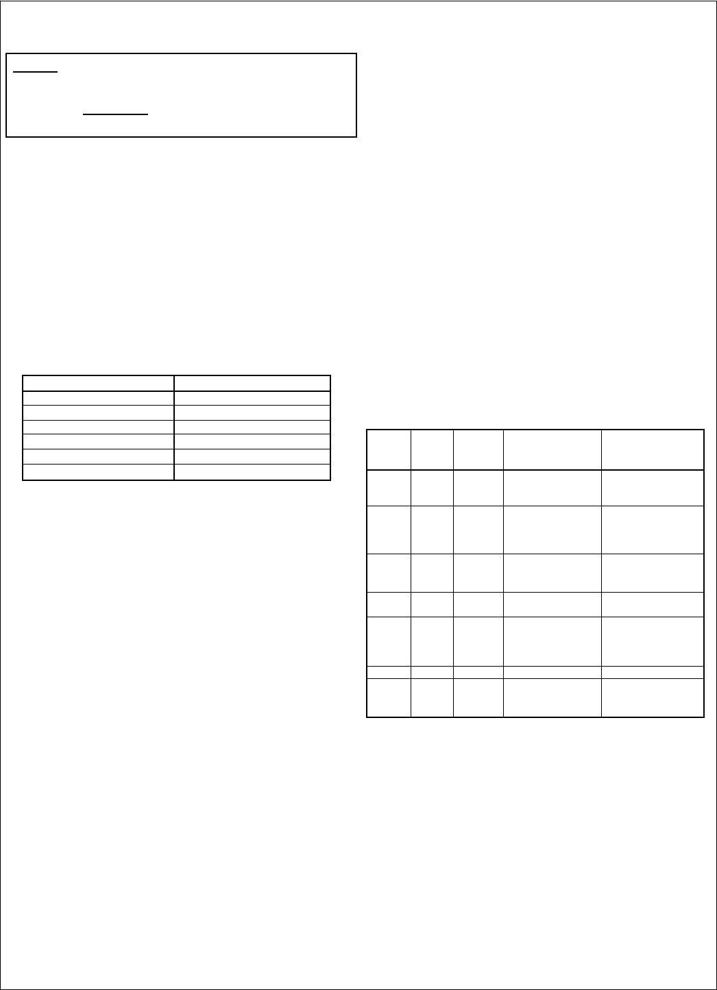
Table 2. Fluid Weight Per Gallon
Percent Glycol Pounds Per Gallon
0
(
Water
)
8.345
10 8.395
20 8.495
30 8.604
40 8.712
50 8.804
bution through the coil as well as flooded suction for the
pump.
3. Water piping must comply with local codes. Correct pipe
sizing will help reduce pumping power and operating costs.
4. In case of doubt, consult the manufacturer for the dry
cooler fluid pressure drop at the specific conditions on
your job.
5. Provide sufficient valves and unions to permit easy ac-
cess to parts subject to wear and possible repair or re-
placement.
6. After fluid piping is completed, all joints should be leak
tested.
7. Where city water makeup is required, follow local codes,
making certain that disconnecting provisions are provided.
8. Select wire in accordance with nameplate data and local
codes.
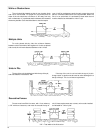
Piping Installation
The piping system should provide maximum leak pre-
vention. Weld or sweat joints should be used where possible
or tightly drawn Teflon tape threaded pipe joints should be made
if needed. The fact that glycol solutions or other heat transfer
fluids will leak where water will not, must be taken into ac-
count.
The glycol system should not employ a pressure reduc-
ing valve. This is because a slight leak would lead to dilution
of the mixture. Any refill should be controlled so as to main-
tain the proper glycol-to-water ratio.
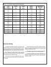
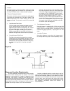
Table 3 shows pressure drops for various pipe sizes at
flow rates commonly used with a typical dry cooler. These
pipe sizes are not necessarily always correct for the run from
the condenser to the dry cooler. Proper pipe size will depend
on available pump head. This can be determined by subtract-
ing from the total available pump head at design flow, the con-
denser pressure drop and the dry cooler pressure drop. Allow
some safety factor for last minute pipe fittings added to the
system and for eventual fouling of the system.
a. Glycol piping requires no insulation except when fluid tem-
perature will be below ambient dewpoint temperatures.
Dry coolers normally produce about 70° or higher fluid
temperatures.
b. Vents are required at all high points in the piping to bleed
air when filling the system. If fluid coolers are at high
points, vent valves should be installed at each fluid cooler.
c. It is recommended that gate valves be installed on
both sides of the pump to prevent loss of fluid in the event
the pump should require repair or replacement. Shut-off
valves are also recommended at water cooled condensers
in case the condensing unit is to be moved or requires
maintenance involving the coolant system.
Table 3. Pressure Loss in Feet of Water
Flow
GPM
Pipe
Size
Steel
Type "L"
O.D.
Copper
Schedule 40 Steel
Head Ft./100 Ft.
Equiv. Length
Copper Tube Head
Head Ft./100 Ft.
Equiv. Length
15 1 1
1
/
8
17.6 15.0
20 1 1
1
/
8 30.2 23.1
25 1 1
1
/
8 — 34.6
25 1
1
/
4 1
3
/
8 11.5 12.6
30 1
1
/
4 1
3
/
8 16.3 17.4
35 1
1
/
4 1
3
/
8 21.8 23.0
40
—
1
3
/
8 — 26.3
40 1
1
/2 1
5
/8 13.0 12.9
45 1
1
/
2 1
5
/
8 16.5 15.7
60
—
1
5
/
8 — 26.3
60 2 2
1
/
8 7.9 7.0
80 2 2
1
/
8 13.7 12.0
100 2
1
/
2 2
5
/
8 8.5
6.1
150 2
1
/
2 2
5
/
8 18.6 12.9
200 3 3
1
/
8 10.7
9.1
250 3 3
1
/
8 16.5 13.7
300 3
1
/
2 3
5
/
8
11.1
9.2
300 4 4
1
/
8 5.9 4.9
350 4 4
1
/
8 7.9 6.5
400 4 4
1
/8 10.2 8.2
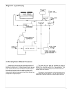
Glycol Charge
The amount of ethylene glycol required depends upon
the following:
a. The holding volume of the system which includes the hold-
ing capacity of the condenser, the holding capacity of the
interconnecting piping (Table 3) and the holding capacity
of the dry cooler (see Table 3).
b. Percentage of glycol required by volume to provide pro-
tection at the design minimum outside temperature (see
Table 2).