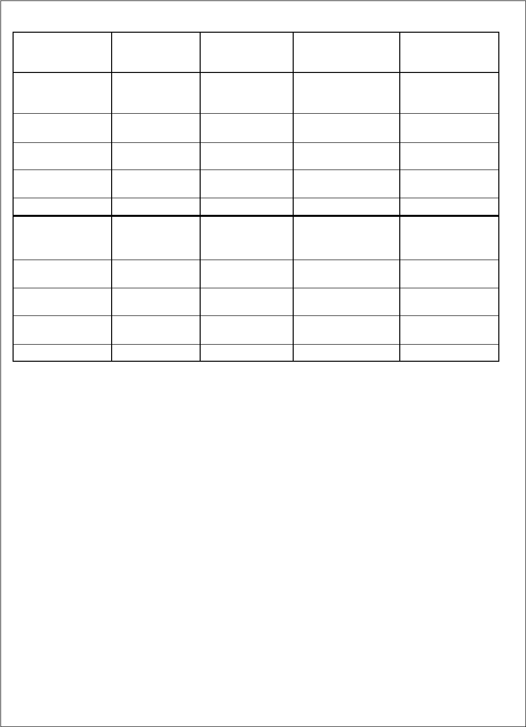
Table 1. Fluid Cooler Internal Volume and Weight
Fluid
Cooler
Fan Configuration
Number
of
Fans
Number
of
Rows
Internal
Volume
Gallons
Approximate
Net Weight
(Lbs.)
1 x 2 2 2 6.7 1540
1 x 2 2 3 9.2 1590
1 x 2 2 4 11.8 1600
1 x 3 3 3 13.0 2360
1 x 3 3 4 16.7 2420
1 x 4 4 3 16.7 3150
1 x 4 4 4 21.7 2190
1 x 5 5 3 20.4 3510
1 x 5 5 4 26.6 3990
1 x 6 6 4 31.6 4790
2 x 2 2 2 13.5 1540
2 x 2 2 3 18.5 1620
2 x 2 2 4 23.5 1760
2 x 3 3 3 25.9 2420
2 x 3 3 4 33.4 2480
2 x 4 4 3 33.3 3230
2 x 4 4 4 43.3 3510
2 x 5 5 3 40.7 4040
2 x 5 5 4 53.1 4390
2 x 6 6 4 63.1 5270
Electrical Wiring
The electrical installation should be in accordance with
National Electrical Code, local codes and regulations. Proper
overcurrent protection should be provided for the fan motors.
Wiring diagrams shown are only basic and do not show fuses,
disconnect switches, etc., which must be provided in the field.
All standard motors have internal inherent overload
protectors. Therefore, contactors can be used instead of
starters requiring thermal protectors, eliminating the problem
of furnishing the proper heating elements.
All dry coolers or units are furnished with either single-
phase or three-phase fan motors which are identified by the
unit dataplate.
Electrical leads from each motor terminate at the unit
junction box. Field connections must be made from these leads
through a contactor, fuse and disconnect in accordance with
local, state and national codes.
Three-phase motors must be connected to three-phase
power of voltage to agree with motor and unit dataplate.
The motors are wired into a common junction box. The
motors must be checked for proper rotation. Be sure to check
that motor voltage and control connection agree with electric
services furnished.


