


9
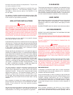
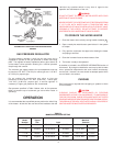
THERMOSTAT FOR NATURAL AND PROPANE GASES
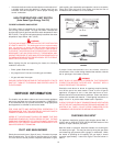
FIGURE 6.
GAS PRESSURE REGULATOR
The gas pressure regulator is built into the gas valve and is
equipped to operate on the gas specified on model and rating
plate. The regulator is factory adjusted to deliver gas to burner at
correct water column pressure allowing for a nominal pressure
drop through the controls.
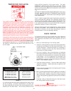
The minimum gas supply pressure for input adjustment must not
be less than 5.0" W.C. (1.24 kPa) for natural gas and 11.0" W.C.
(2.74 kPa) for propane gas.
Do not subject the combination gas valve to inlet gas
pressures of more than 14.0" W.C. (3.48 kPa) - natural gas,
14.0" W.C. (3.48 kPa)- propane gas. A service regulator is
necessary if higher gas pressures are encountered.
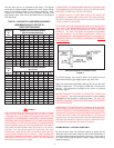
Gas pressure specified in Table 2 below, refer to flow pressure
taken at pressure tap of automatic gas valve while heater is
operating.
OPERATION
It is recommended that a qualified person perform the initial firing
of the heater. At this time the user should not hesitate to ask the
individual any questions which he may have in regard to the
operation and maintenance of the unit.
WARNING
DO NOT ATTEMPT TO OPERATE WATER HEATER WITH COLD
WATER INLET VALVE CLOSED.
NEVER OPERATE THE HEATER WITHOUT FIRST BEING CERTAIN
IT IS FILLED WITH WATER AND A TEMPERATURE AND
PRESSURE RELIEF VALVE IS INSTALLED IN THE RELIEF VALVE
OPENING OF THE HEATER. DO NOT ATTEMPT TO OPERATE
HEATER WITH COLD WATER INLET VALVE CLOSED.
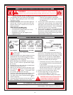
TO OPERATE THE WATER HEATER
1. Close the heater drain valve by turning handle clockwise .
2. Open a nearby hot water faucet to permit the air in the system
to escape.
3. Fully open the cold water inlet pipe valve allowing the heater
and piping to be filled.
4. Close the hot water faucet as water starts to flow.
5. The heater is ready to be operated.
A checklist is included in the SERVICE INFORMATION section of
this manual. By using this checklist the user may be able to make
minor operational adjustments and save himself unnecessary
service calls. However, the user should not attempt repairs which
are not listed in this section.
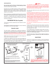
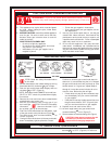
PURGING
Gas line purging is required with new piping or systems in which
air has entered.
CAUTION
PURGING SHOULD BE PERFORMED BY PERSONS
EXPERIENCED IN THIS TYPE GAS SERVICE. TO AVOID RISK OF
FIRE OR EXPLOSION, PURGE DISCHARGE MUST NOT ENTER
CONFINED AREAS OR SPACES WHERE IGNITION CAN OCCUR.
THE AREA MUST BE WELL VENTILATED AND ALL SOURCES OF
IGNITION MUST BE INACTIVATED OR REMOVED.
TABLE 2.
MANIFOLD PRESSURE SETTING
Model Type of Manifold
Number Gas Input Pressure
***-75 Natural 75,100 Btu/hr 22 kW/hr 4.0 in. W.C. 1.0 kPa
***-75 Propane 75,100 Btu/hr 22 kW/hr 10.0 in. W.C. 2.5 kPa
***-100 Natural 75,100 Btu/hr 22 kW/hr 4.0 in. W.C. 1.0 kPa
***-100 Propane 75,100 Btu/hr 22 kW/hr 10.0 in. W.C. 2.5 kPa