


7
VENT CONNECTION
Vent connections must be made to an adequate stack or chimney.
Size and install proper size vent pipe. Do not reduce pipe size to
less than that of the draft hood outlet.
Horizontal runs of vent pipe must have a minimum upward slope
toward the chimney of 1/4 inch per foot. Dampers or other
obstructions must not be installed in between the heater and the
draft hood. Be sure that the vent pipe does not extend beyond the
inside wall of the chimney.
Where a continuous or intermittent back draft is found to exist, the
cause must be determined and corrected. A special vent cap may
be required. If the back draft cannot be corrected by the normal
methods or if a suitable draft cannot be obtained, a blower type
flue gas exhauster must be employed to assure proper venting
and correct combustion.
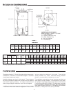
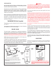
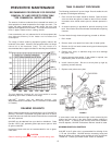
THERMOMETERS (Not Supplied)
Thermometers should be obtained and field installed as shown,
see Figure 4.
Thermometers are installed in the system as a means of detecting
the temperature of the outlet water supply.
RELIEF VALVE
This water heater is equipped with a combination temperature-
pressure relief valve that complies with the standard for relief valves
and automatic gas shutoff devices for hot water supply system,
ANSI Z21.22. FOR SAFE OPERATION OF THE WATER HEATER,
THE RELIEF VALVE(S) MUST NOT BE REMOVED OR PLUGGED.
ASME ratings cover pressure relief capacities. A.G.A. ratings cover
release rate with temperature actuation.
In addition to the appliance relief valve, each remote storage tank
which may be used in conjunction with this appliance shall also
be installed with a properly sized, rated and approved combination
temperature (ANSI) and pressure (ASME) relief valve(s).
WARNING
THE PURPOSE OF RELIEF VALVE IS TO AVOID EXCESSIVE
PRESSURE OR TEMPERATURE INTO THE STEAM RANGE,
WHICH MAY CAUSE SCALDING AT FIXTURES, TANK EXPLOSION,
SYSTEM OR HEATER DAMAGE. NO VALVE IS TO BE PLACED
BETWEEN THE RELIEF VALVE AND TANK.
Your local code authority may have other specific relief valve
requirements.
A DRAIN LINE MUST BE CONNECTED TO THE RELIEF VALVE TO
DIRECT DISCHARGE TO A SAFE LOCATION TO AVOID SCALDING
OR WATER DAMAGE. THIS LINE MUST NOT BE REDUCED FROM
THE SIZE OF THE VALVE OUTLET AND MUST NOT CONTAIN
VALVES, RESTRICTIONS NOR SHOULD IT BE LOCATED IN
FREEZING AREAS. DO NOT THREAD OR CAP THE END OF THIS
LINE. RESTRICTED OR BLOCKED DISCHARGE WILL DEFEAT
THE PURPOSE OF THE VALVE AND IS UNSAFE. DISCHARGE
LINE SHALL BE INSTALLED TO ALLOW COMPLETE DRAINAGE
OF BOTH THE VALVE AND LINE.
See SERVICE INFORMATION section for procedure and
precautions.
The type, size and location of the relief valves must be in accordance
with local codes. The locations of the relief valves shown in the
installation diagrams are typical. The heater has a factory installed
high temperature limit switch.
For circulating heaters, the separate storage vessel must have a
temperature and pressure relief valve installed. This valve shall
comply with the standard for relief valves and automatic gas shutoff
devices for hot water supply systems.
Cold water inlet lines to heater should be installed as shown in
order to minimize gravity circulation of hot water to building cold
water lines.
GAS PIPING
Contact your local gas service company to ensure that adequate
gas service is available and to review applicable installation codes
for your area.
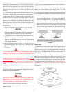
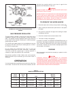
FIGURE 4.
CIRCULATING RETURN LINE CONNECTIONS
TEMPERED WATER LOOP, IF USED, CONNECT TO POINT "A".
STORED TEMPERATURE WATER LOOP, IF USED, CONNECT TO
COLD WATER INLET.
CAUTION: IF BUILDING COLD WATER SUPPLY HAS A BACK-
FLOWPREVENTER, CHECK VALVE OR WATER METER WITH CHECK
VALVE, PROVISIONS FOR THERMAL EXPANSION OF WATER IN THE
HOT WATER SYSTEM MUST BE PROVIDED.
WARNING
TEMPERATURE SETTING SHOULD NOT EXCEED SAFE USE TEMPERATURE
AT FIXTURES. SEE TEMPERATURE REGULATION ON PAGE 4. IF HIGHER
PREHEAT TEMPERATURES ARE NECESSARY TO OBTAIN ADEQUATE
BOOSTER OUTPUT, ADD AN ANTI-SCALD VALVE FOR HOT WATER SUPPLIED
TO FIXTURES.
SINGLE TEMPERATURE
MIXING VALVE APPLICATION FOR
TWO TEMPERATURE WATER
VACUUM RELIEF
VALV E
*INSTALL PER
LOCAL CODES