


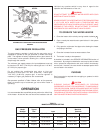

6
OR WITHIN 12 INCHES (305mm) OF THE ENCLOSURE TOP AND
ONE IN OR WITHIN 12 INCHES (305mm) OF THE ENCLOSURE
BOTTOM. Each opening shall have a free area of at least one
square inch per 1000 Btuh (2203mm
2
/kW) of the total input of all
appliances in the enclosure, but not less than 100 square inches
(645cm
2
).
If the confined space is within a building of tight construction, air for
combustion, ventilation, and draft hood dilution must be obtained
from outdoors. When directly communicating with the outdoors or
communicating with the outdoors through vertical ducts, two
permanent openings, located in the above manner, shall be
provided. Each opening shall have a free area of not less than one
square inch per 4000 Btuh (551mm
2
/kW) of the total input of all
appliances in the enclosure. If horizontal ducts are used, each
opening shall have a free area of not less than one square inch
per 2000 Btuh (1102mm
2
/kW) of the total input of all appliances in
the enclosure.
WATER (POTABLE) HEATING AND SPACE
HEATING
1. All piping components connected to this unit for space heating
applications shall be suitable for use with potable water.
2. Toxic chemicals, such as those used for boiler treatment, shall
NEVER be introduced into this system.
3. This unit may NEVER be connected to any existing heating
system or component(s) previously used with a non-potable
water heating appliance.
4. When the system requires water for space heating at
temperatures higher than required for domestic water
purposes, a tempering valve must be installed. Please refer
to Figure 4.
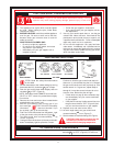
CAUTION
A closed system will exist if a check valve (without bypass), pressure
reducing valve (without bypass), or a water meter (without bypass)
is installed in the cold water line between the water heater and
street main (or well).
Excessive pressure may develop in such closed systems, causing
premature tank failure or intermittent relief valve operation.
This is
not a warranty failure. An expansion tank or a similar device is
required in the inlet supply line between the appliance and the
meter or valve to compensate for the thermal expansion of the
water.
SYSTEM CONNECTIONS
The system installation must conform to these instructions and to
the local code authority having jurisdiction. Good practice requires
that all heavy piping be supported.
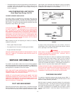
VENTING
WARNING
THE INSTRUCTIONS IN THIS SECTION ON VENTING MUST BE
FOLLOWED TO AVOID CHOKED COMBUSTION OR
RECIRCULATION OF FLUE GASES. SUCH CONDITIONS CAUSE
SOOTING OR RISKS OF FIRE AND ASPHYXIATION.
Heater must be protected from freezing downdrafts.
Remove all soot or other obstructions from the chimney that will
retard a free draft.
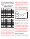
Type B venting is recommended with these heaters. See table Vl
FOR TYPICAL VENTING APPLICATION.
This water heater must be vented in compliance with all local
codes, the current edition of the National Fuel Gas Code
(ANSI-Z223.1) and with the Category I Venting Tables.
If any part of the vent system is exposed to ambient temperatures
below 35 degrees F (2 degrees C) it must be insulated to prevent
condensation.
• Do not connect the heater to a common vent or chimney with
solid fuel burning equipment. This practice is prohibited by
many local building codes as is the practice of venting gas
fired equipment to the duct work of ventilation systems.
• Where a separate vent connection is not available and the vent
pipe from the heater must be connected to a common vent
with an oil burning furnace, the vent pipe should enter the
smaller common vent or chimney at a point above the large
vent pipe.
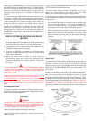
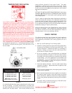
FIGURE 2
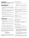
DRAFT HOOD
The draft hood furnished with this heater must be installed without
alteration. Provision must be made if it is installed in confined
space or a small room to accommodate draft hood spillage and
avoid risks described in previous steps. The upper air opening
called for in the AIR REQUIREMENTS section of this manual is for
this purpose.
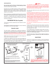
Locate the 3 brackets and 6 screws in the installation instruction
bag. Secure each bracket to the draft hood leg with the screws
furnished. Place the draft hood on the water heater so that legs of
the draft hood fit into the slots on the jacket top, see figure 3. Once
the draft hood (with brackets attached) is in place, drill a small pilot
hole through bracket hole into the jacket top.
WARNING, DO NOT
PENETRATE THE JACKET TOP BY MORE THAN 1/4" (6.4 mm).
Secure the brackets to the jacket top with the screws furnished,
see Figure 3.
FIGURE 3.