


27
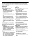
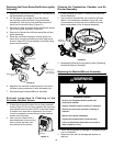
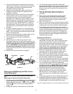
3. Insert the manifold/burner assembly into the burner
compartment making sure that the tip of the manifold
tube engages in the slot of the bracket inside the
combustion chamber (Figure 29).
4. Inspect the door gasket and make sure there is no
fiberglass insulation between the gasket and the
combustion chamber.
5. Replace the two screws, which secure the manifold/
burner assembly door to the combustion chamber
and tighten securely. Once the manifold/burner
assembly door is tightened, visually inspect the door
gasket between the manifold/burner assembly door
and the combustion chamber for spaces or gaps that
would prevent a seal. IMPORTANT: Do not operate
the water heater if the door gasket does not create a
seal between the manifold door and the combustion
chamber.
6. During the following procedure, do not cross-thread
or apply any thread sealant to any of the fittings listed
below. First, reconnect the manifold tubing to the gas
control valve/thermostat.
7. Reconnect the flame sense/hot surface igniter wire to
the gas control valve/thermostat (Figure 24).
8. Turn gas supply on and refer to the Lighting
Instructions.
9. With the burner lit, check the gas control valve/
thermostat supply line, two piece wire connector, and
manifold tube connections for leaks. Check for leaks by
brushing on an approved noncorrosive leak detection
solution. IMPORTANT: Do Not splash solution onto
the electrical connections. Bubbles forming indicate
a leak. Correct any leak found. All leaks must be fixed
immediately.
10. Replace the outer door (see item K page 5).
Door Gasket
Viewport
Manifold Tab
Slot
Burner
FIGURE 29.
Removing and Replacing the Gas Control
Valve/Thermostat
IMPORTANT: Use only factory authorized replacement
parts.
Removing the Gas Control Valve/Thermostat:
1. Set the gas control valve/thermostat to its lowest setting
by first depressing the COOLER and HOTTER
buttons together and hold for 1 second. Then press the
COOLER button until the lowest setting appears
(Figure 21).
2. Unplug the electrical transformer from the wall outlet.
3. Turn off the gas supply to the water heater at the
manual gas shut-off valve. This valve is typically located
beside the water heater. Note the position of the shut-
off valve in the open/on position then proceed to turn it
off (Figure 3).
4. Drain the water heater. Refer to the section of
“Draining and Flushing” section and follow the
procedure.
5. Disconnect the the flame sense/hot surface igniter
wire, power supply transformer, pressure switch/
fan and display connector wires from the thermostat
(Figure 24). Disconnect the manifould tube at the
thermostat (Figure 24).
6. Refer to “Gas Piping” section (Figure 3) and disconnect
the ground joint union in the gas piping. Disconnect the
remaining pipe from the gas control valve/thermostat.
7. To remove the gas control valve/thermostat, thread a
correctly sized pipe into the inlet and use it to turn the gas
control valve/thermostat (counterclockwise.) Do not use
pipe wrench or equivalent to grip body. Damage may
result, causing leaks. Do not insert any sharp objects into
the inlet or outlet connections. Damage to the gas control
valve/thermostat may result.
Replacing the Gas Valve:
1. To replace the gas control valve/thermostat,
reassemble in reverse order. When replacing the gas
control valve/ thermostat, thread a correctly sized
pipe into the inlet and use it to turn the gas valve
(clockwise.) DO NOT OVER TIGHTEN or damage may
result. NOTE: Use an approved
TEFLON
®
tape or pipe
compound only on the threaded section of the gas
control valve/thermostat that screws into the tank.
2. Reconnect the gas piping to the gas control valve/
thermostat. NOTE: Use an approved Teflon tape or
pipe compound on the gas piping connections.
3. Reconnect the manifold tube, flame sense/hot surface
igniter wire, power supply transformer, pressure switch/
fan and display connector wires (Figure 24).
4. Fill the tank completely with water. NOTE: To purge the
lines of any excess air, keep the hot water faucet open
for 3 minutes after a constant flow of water is obtained.
5. Turn on the gas supply and test the gas supply
connections by brushing on an approved noncorrosive
leak detection solution. IMPORTANT: Do Not splash
solution onto the electrical connections. Bubbles
forming indicate a leak. Correct any leak found.
6. Check the operation of the burner by following the
lighting instructions on the front of the water heater.
With the burner lit, check the gas control valve/
thermostat supply line, manifold tube connections for
leaks.
7. Verify proper operation and then replace the outer door.
8. If additional information is required, contact Residential
Technical Assistance by referencing the phone number on
the water heater or on the front cover of this manual.
TEFLON
®
is a registered trademark of E.I. Du Pont De Nemours and Company