


14
Align the legs of the draft hood with the slots provided.
Insert the legs and secure the draft hood to the water
heater’s top with the four screws provided as shown in
Figure 9. Do not alter the draft hood in any way. If you are
replacing an existing water heater, be sure to use the draft
hood supplied with this water heater.
Vent Pipe Size
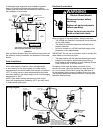
It is important that you follow the guidelines in these
instructions for sizing a vent pipe system. If a transition
to a larger vent size is required, the vent transition
connection must be made at the draft hood outlet.
Vent Connectors
1. Type B, Double wall, U.L. Listed Vent Pipe.
2. Single wall Vent Pipe.
Maintain the manufacturer’s specified minimum clearance
from combustible materials when using type B double wall
vent pipe.
Vent connectors made of type B, double wall vent pipe
material may pass through walls or partitions constructed
of combustible material if the minimum listed clearance is
maintained.
Maintain a six inch minimum clearance from all
combustible materials when using single wall vent pipe.
IMPORTANT: Single wall vent pipe cannot be used for
water heaters located in attics and may not pass through
attic spaces, crawl spaces or any confined or inaccessible
location. A single wall metal vent connector cannot pass
through any interior wall.
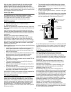
When installing a vent connector, please note the following
(See Figures 10-12):
• Install the vent connector avoiding unnecessary bends,
which create resistance to the flow of vent gases.
• Install without dips or sags with an upward slope of at
least 1/4-inch per foot.
• Joints must be fastened by sheet metal screws or other
approved means. It must be supported to maintain
clearances and prevent separation of joints and
damage.
• The length of the vent connector cannot exceed 75% of
the vertical vent height.
• The vent connector must be accessible for cleaning,
inspection, and replacement.
• Vent connectors cannot pass through any ceiling, floor,
firewall, or fire partition.
• It is recommended (but not mandatory) that a minimum
12 inches of vertical vent pipe be installed on the draft
hood prior to any elbow in the vent system.
IMPORTANT: Existing vent systems must be inspected for
obstructions, corrosion, and proper installation.
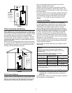
Chimney Connection
IMPORTANT: Before connecting a vent to a chimney,
make sure the chimney passageway is clear and free of
obstructions. The chimney must be cleaned if previously
used for venting solid fuel appliances or fireplaces. Also
consult local and state codes for proper chimney sizing
and application or, in the absence of local and state
codes, the “National Fuel Gas Code”, ANSI Z223.1(NFPA
54)-current edition.
• The connector must be installed above the extreme
bottom of the chimney to prevent potentially blocking
the flue gases.
• The connector must be firmly attached and sealed to
prevent it from falling out.
• To aid in removing the connector, a thimble or slip joint
may be used.
• The connector must not extend beyond the inner edge
of the chimney as it may restrict the space between it
and the opposite wall of the chimney (Figure 10).
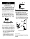
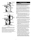
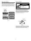
Chimney Termination Vent System
Seal
Do Not Extend
Vent Beyond Edge
Of Chimney
Maintain
Clearance*
Support Strap
3 FT.
Minimum
2 FT. Minimum Above Any Object
Within 10 FT. Horizontally
Slope Up
1/4 Inch
Per Foot
Minimum
Vent
Connector
FIGURE 10.
Do not terminate the vent connector in a chimney that has
not been certified for this purpose. Some local codes may
prohibit the termination of vent connectors in a masonry
chimney.
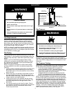
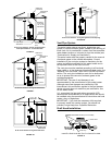
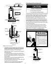
Vertical Exhaust Gas Vent
Vertical exhaust gas vents must be installed with
U.L. listed type B vent pipe according to the vent
manufacturer’s instructions and the terms of its listing.
It must be connected to the water heater’s draft hood by a
listed vent connector or by directly originating at the draft
hood opening.
Vertical gas vents must terminate with a listed cap or
other roof assembly and be installed according to their
manufacturer’s instructions.
Gas vents must be supported to prevent damage, joint
separation, and maintain clearances to combustible
materials (Figures 11 and 12).
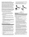
IMPORTANT: This gas vent must be terminated in a
vertical position to facilitate the removal of the burnt gases.
An unused chimney flue or masonry enclosure may be used
as a passageway for the installation of a gas vent (Figure 12).
Common (combined) venting is allowable with vertical type
B vent systems and lined masonry chimneys as long as
proper draft for the water heater is established under all
conditions of operation. CAUTION: DO NOT common vent
this water heater with any power vented appliance.
Figures 10-12 are examples of vent pipe system
installations and may or may not be typical for your
specific application. Consult the “National Fuel Gas Code”,
NFPA 54, ANSI Z223.1-current edition and the guidelines
set forth by prevailing local codes.