


25
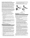
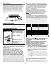
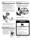
properly. To prevent water damage, the valve must be pro-
perly connected to a discharge line which terminates at an
adequate drain. Standing clear of the outlet (discharged
water may be hot), slowly lift and release the lever handle
on the temperature and pressure relief valve to allow the
valve to operate freely and return to its closed position.
See Figure 23. If the valve fails to completely reset and
continues to release water, immediately shut off the
manual gas control valve and the cold water inlet valve
and call a qualified technician.
TEMPERATURE AND PRESSURE
RELIEF VALVE
DISCHARGE LINE TO DRAIN
MANUAL RELIEF
VALVE
FIGURE 23.
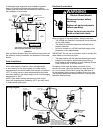
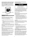
FIGURE 24.
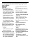
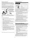
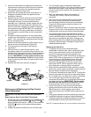
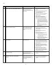
Removing the Burner from the Manifold/
Burner Assembly
Natural Gas Burner
1. Take off the burner by removing the two (2) screws
located underneath the burner.
2. Check the burner to see if it is dirty or clogged. The burner
may be cleaned with soap and hot water (Figure 25).
FIGURE 25.
Replacement Parts
IMPORTANT: The following maintenance procedures are
for the FVIR System components and should be performed
by a qualified technician.
Replacement parts may be ordered through your plumber
or the local distributor. Parts will be shipped at prevailing
prices and billed accordingly. When ordering replacement
parts, always have the following information ready:
1. model, serial, and product number
2. type of gas
3. item number
4. parts description
See Repair Parts Section for a list of available repair parts.
Removing the Manifold/Burner Assembly
1. Turn off the gas supply to the water heater at the manual
gas shut-off valve. This valve is typically located beside
the water heater. Note the position of the shut-off valve in
the open/on position then proceed to turn it off (Figure 3).
2. Disconnect power supply to the heater.
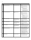
3. Remove the outer door. Remove the 2 screw securing
the manifold door assembly to the skirt.
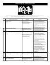
4. Disconnect all wiring connectors from the gas control
valve/thermostat (Figure 24). Disconnect the manifold
tube at the gas control valve/thermostat.
5. Grasp the manifold tube and push down slightly to free
the manifold from the gas control valve/thermostat.
6. Carefully remove the manifold assembly from the burner
compartment. NOTE: Be sure not to damage internal
parts (Figure 28).
7. Check the burner to see if it is dirty or clogged. The
burner may be cleaned with soap and hot water.
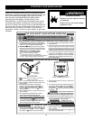
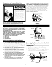
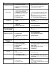
Temperature and Pressure Relief Valve
Explosion Harzard
• Temperature-pressure relief
valve must comply with ANSI
Z21.22-CSA 4.4 and ASME
code.
• Properly sized temperature-
pressure relief valve must be
installed in opening provided.
• Can result in overheating
and excessive tank pressure.
• Can cause serious injury or
death.
Manually operate the temperature and pressure relief
valve at least once a year to make sure it is working
MAINTENANCE OF YOUR WATER HEATER
Manifold Tube
Control Display,
Anode Rod
Connector
Pressure
Switch / Fan,
FV Sensor
Connector
Power Supply
Transformer
Connector
Igniter/Flame
Sense
Connector
Gas Control Valve/
Thermostat
Burner
(Bottom View)
Screws
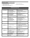
Manifold Door Assembly
Igniter/Flame
Sense Connector
View Port