


18
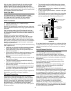
A diaphragm-type expansion tank suitable for potable
water will normally eliminate this weeping condition.
Please read and follow the manufacturer’s instructions for
the installation of such tanks.
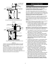
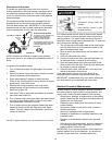
MASSACHUSETTS CODE
DOES NOT ALLOW THIS
TYPE OF INSTALLATION.
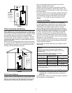
Must Be Vertical To
Remove Air Bubbles
Domestic
Hot Water
Out
Mixing
Valve
Hot
Water
Out
Unions
To Air
Handler
Vacuum
Relief
Valve
Expansion Tank
Cold Water Inlet
Flow Control
Pump
Valve
In
Out
Coil
Air
Handler
Shut-Off
Valve
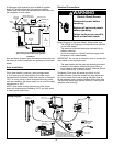
Typical Mixing Valve Installation Combination
Space Heating/Potable Water Heating System
FIGURE 16
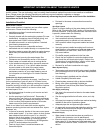
Electrical Connections
Before plugging in the water heater, always make sure:
• The Voltage and frequency correspond to that specified
on the water heater.
• The electrical outlet has the proper overload fuse or
breaker protection.
• Unit is to connect to a 120VAC electrical supply outlet
(extension cord is not allowed).
IMPORTANT: Do not use an extension cord to connect the
water heater to an electrical outlet.
• The water heater and the outlet are properly grounded.
• Installed in accordance with prevailing provisions of
local codes, or in the absence of such, National Electric
Code, ANSI/NFPS 70 current edition.
Completely fill the tank with water and check all con-
nections for leaks. Open the nearest hot water faucet and
let it run for three (3) minutes to purge the water lines of
air and sediment and to ensure complete filling of the tank.
The Electrical power may then be turned on. Verify proper
operation after servicing.
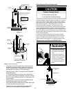
WARNING
Electric Shock Hazard
Disconnect power before
servicing.
Replace all parts and panels
before operating.
Failure to do so can result in
death or electrical shock.
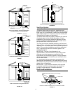
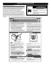
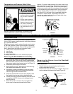
Pressure
Switch
Control Display
Power Supply
Transformer
Igniter/Flame
Sense Connector
Air Intake
Chamber Fan
Anode
Rod
Gas Control
Valve / Thermostat
CAUTION:
LABEL ALL WIRES PRIOR TO
DISCONNECTION WHEN SERVICING
CONTROLS. WIRING ERRORS CAN CAUSE
IMPROPER AND DANGEROUS OPERATION.
VERIFY PROPER OPERATION AFTER SERVICING.
FV
Sensor
CAUTION:
DO NOT USE AN EXTENSION
CORD TO CONNECT THE
TRANSFORMER TO AN
ELECTRICAL OUTLET.
Also see Water System Piping for additional instructions on
the safe and correct installation and operation of this water
heater.
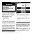
Solar Installation
If this water heater is used as a solar storage heater
or as a backup for the solar system, the water supply
temperatures to the water heater tank may be in excess of
120°F. A mixing valve or other temperature limiting valve
must be installed in the water supply line to limit the supply
temperature to 120°F.
NOTE: Solar water heating systems can often supply
water with temperatures exceeding 180°F and may result
in water heater malfunction.
Wiring Diagram