GS110 DIRECT VENT BOILER INSTALLATION AND OPERATION INSTRUCTIONSPage 26
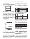
Main Burner Flame
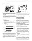
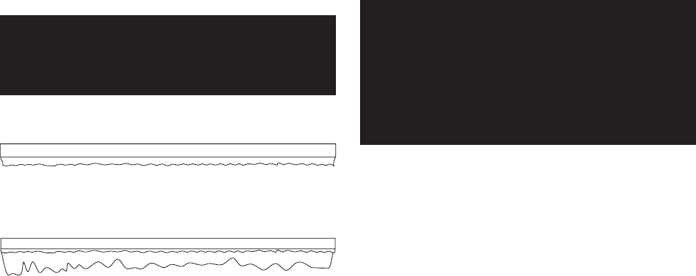
A properly adjusted main burner flame will produce a
tight blue flame pattern about 1/2 inch tall from the
burner’s surface, Figure 21. A yellow floating or tall
stringy flame is not normal and must be corrected.
WARNING: Yellow, floating flames indicate a lack
of combustion air. DO NOT operate the boiler
until the problem is solved or severe personal
injury or death may occur!
Figure 21 - Burner Flame
Thermostat Adjustment
Set the heat anticipator to 1.1 amps when controlling
the boiler directly. For zoned systems set the heat
anticipator to match the amp draw of the zone valves
or pump relays.
BOILER MAINTENANCE
The boiler should be cleaned and inspected once a
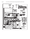
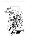
year, before each heating season. Refer to Figures 22
for component identification
CAUTION: Servicing, inspection and adjustment
must be done by a trained technician in accordance
with all applicable local and national codes.
Improper servicing or adjustment could damage the
boiler!
Control Panel
Use a soft brush and/or a vacuum cleaner to ensure that
the electrical components are free from dust or deposits
that would impair the boiler's performance.
Air Filter
1. Remove the front jacket panel.
2. Remove the filter box cover and filter.
3. Wash the filter in warm water. Shake out all excess
moisture before reinstalling.
Burner Box Removal & Replacement
CAUTION: The burner box should not be removed!
Careless handling can damage the burner.
WARNING: The ceramic combusiton chamber in
the burner box and its gasket contain crystalline
silica. Wear a tightly fitted dust mask when
servicing the burner and gently handle the
burner and its gasket to prevent inhalation of
airborne fibers. Crystalline silica fibers have
been identified as carcinogenic, or possibly
carcinogenic when inhaled.
If you suspect a problem within the burner assembly,
please contact a local manufacturer representative.
Condensate System
Ensure that the condensate removal system is sound
and working properly.
Vent System
The entire vent system must be thoroughly inspected
for any signs of blockage, corrosion or leaks.
Immediately replace any unsound vent system piping.
Remove any foreign matter in or near the vent terminal
or around the boiler that might obstruct the flow of
combustion and ventilation air.
Blower Motor
Every 3 to 6 months, lubricate the inducer motor using
2 drops of 20W non detergent motor oil in each oil port.
Low Water Cutoff
If the boiler has been equipped with a low water cut-
off device, follow the manufacturer's instructions for
cleaning and to confirm proper operation
Relief Valve
The relief valve should vent water when the test lever
is lifted. It should not weep or discharge water at normal
system pressure. NEVER try to clean or repair the relief
valve! If the valve fails replace it!
Aquastat High Limit
The aquastat high limit controls the maximum water
temperature in the boiler. It is adjustable from 140°F
(60°C) to 220°F (104°C). If the water temperature
reaches the set temperature before the demand for heat
has been met, the aquastat high limit should shut the
burners off. The outlet water temperature should never
exceed 220°F (104°C). If the aquastat high limit fails to
function properly replace it.
TIGHT BLUE FLAME
YELLOW FLOATING FLAME


