GS110 DIRECT VENT BOILER INSTALLATION AND OPERATION INSTRUCTIONS Page 19
installed in Canada. Install a separate 120 volt 15 amp
circuit for the boiler. A properly rated shut-off switch
should be located at the boiler. The boiler must be
grounded in accordance with the authority having
jurisdiction, or if none, the latest revision of the National
Electrical Code, ANSI/NFPA-70.
Line voltage field wiring of any controls or other devices
must use copper conductors with a minimum size of #14
awg. Low voltage wiring must not be less than #18 awg
with a neoprene, thermoplastic or other equivalent
insulation having a minimum insulation thickness of
0.012 inches.
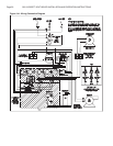
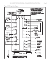
Refer to Figures 19A and 19B for proper wiring
connections.
Thermostat Installation
ALWAYS follow the instructions included with the ther-
mostat to be used to control the boiler. Proper location
of the thermostat will ensure efficient trouble-free
operation of the boiler. Mount the thermostat to an inside
wall at a height approximately five feet above the floor.
Avoid placing the thermostat in areas that will not pro-
vide an accurate measurement of the room temperature.
Locating the thermostat behind a door, in an alcove,
close to a source of thermal radiation or in a drafty area
will cause poor or sporadic heating.
OPERATIONAL SEQUENCE
The control energizes the circulator motor when the
thermostat contacts are closed. The control then checks
that the limit switch is closed, if not the control will wait
for the limit switch to close. With the limit switch closed
the pressure switch contacts are checked. If the
pressure switch contacts are open the blower motor is
energized. If the pressure switch contacts aren’t open
the control will wait 45 seconds then lock out. The
PURGE light will flash to indicate a pressure switch fault.
Also, if the pressure switch does not close within 5
minutes of the blower being turned on, the control will
lock out with the PURGE light flashing to indicate a
pressure switch fault.
The pre-purge period begins when the pressure switch
contacts close. At the end of the pre-purge period, the
control energizes the HSI igniter for an HSI warm-up
period. This condition will be indicated by illumination of
the IGNITER light. A one second trial for ignition will take
place. In the event ignition is not achieved by the end of
the first trial for ignition period, the control will run through
a post purge and then de-energize the inducer. When
the pressure switch contacts open the control will begin
a new ignition sequence. Failure to establish flame after
the third attempt will result in ignition lock-out and the
VALVE light on the control will flash.
Once the flame has been proven, the system is in
Steady-State heating mode. The control will continuously
monitor the thermostat, limit switch, pressure switch, and
flame sense. If the thermostat opens, the control will
de-energize the gas valve and begin post-purge. If the
limit switch opens, the control will de-energizes the gas
valve, run through post-purge, and wait for the limit
switch to re-close before attempting re-ignition. If flame
is lost, the control will de-energize the gas valve, run
through post-purge, and go to pressure switch proving
mode for re-ignition. If the pressure switch opens for
more than 0.1 seconds the inducer is turned off for 30
seconds, then the control goes to the pressure switch
proving mode for a re-ignition attempt.
When the thermostat is satisfied the post purge period
starts. A post-purge will be performed at any time the
gas valve has been on and is turned off, except for loss
of pressure switch, when a post-purge would be
ineffective. The post-purge must be completed before a
new ignition sequence can start.
In the event that the flame signal is lost after the flame
has been proven, the system will turn off the gas valve
within 2.0 seconds, perform the post-purge, and repeat
the ignition sequence. As a preventative measure to
avoid nuisance shutdown due to a flickering flame, the
flame must be lost for a minimum of 0.5 seconds.
Control Outputs:
Induced draft blower - 1.75 Amps @ 120 VAC.
Circulator Pump - 2.7 Amps @ 120 VAC.
Hot Surface Igniter - 5.0 Amp resistive @ 120 VAC.
Gas Valve - 0.6 Amp @ 24 VAC, 0.45 power factor.


