GS110 DIRECT VENT BOILER INSTALLATION AND OPERATION INSTRUCTIONS Page 15
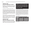
WARNING: Failure to connect a condensate trap
or pump to the flue collector can result in
excessive levels of carbon monoxide which can
cause severe personal injury or death!
HEATING SYSTEM PIPING
CAUTION: All heating system piping must be
installed in accordance with the ANSI/ASME Boiler
and Pressure Vessel Code, Section IV. All applicable
local codes and ordinances must also be followed.
If the boiler is installed above any radiation
elements it must be fitted with a low water cutoff
device installed above the normal boiler water level!
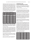
The GS110 hot water boiler comes from the factory
ready to be piped to the heating system. Each boiler is
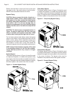
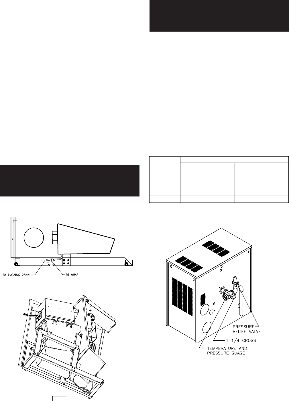
equipped with a safety relief valve which must be piped
in accordance with the ANSI/ASME Boiler and Pressure
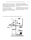
Vessel Code, Section IV, see Figure 13.
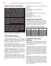
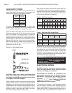
Table 7 - Boiler Water Volume
* 1-1/2 " Supply and Return Tappings
Figure 13 - Relief Valve Piping
Liters Gallons
Boiler
Model
6.8
9.1
11.4
13.6
15.9
1.8
2.4
3.0
3.6
4.2
GS110-3
GS110-4
GS110-5
GS110-6
GS110-7
Water Volume
Tout mauvais fonctionnement du systéme d'évacu-
tion commun devrait étré corrigé de façor que
l'installation soit conforme au National Fue Gas Code,
ANSI Z223.1/NFPA 54 et (ou) aux codes d'in-
stallation CSA-B149. Si la grosseur d'une section du
système d' évacuation doit étré modifiée, le système
devrait étré modifié pour respecter les valeurs
minimales des tableaux pertinents de l'appendice F
du National Fuel Gas Code, ANSI Z223.1/ NFPA 54
et (ou) des codes d'installation CSA-B149.
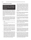
CONDENSATE PIPING
A small amount of condensate is generated on start up.
To prevent an excess amount of condensate collecting
in the flue collector a condensate drain has been
provided. A condensate trap or pump MUST be
connected to the condensate fitting in the bottom of the
flue collector.
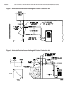
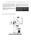
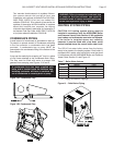
A trap can be made by tie wrapping a 4” loop in a piece
of vinyl hose attached to the condensate drain fitting.
The trap must be filled with water to prevent flue
gassses from escaping, see Figures 12 A and B.
A condensate hose has been supplied with
boiler and is located inside the literature bag.
Installing contractor will have to continue the
run of condensate to a nearby drain or pump.
Figure 12A- Condensate Trap
Figure 12B- Condensate Trap
SIOM-75


