


I
NTREPID
7
C. HOT WATER RADIATION VENTING - Manual air vents should be
installed at the top of all "drops"(where piping goes downward).
Air must be vented or purged from all zone lines to permit proper
system heating.
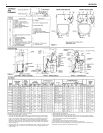
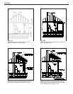
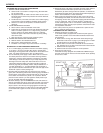
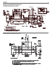
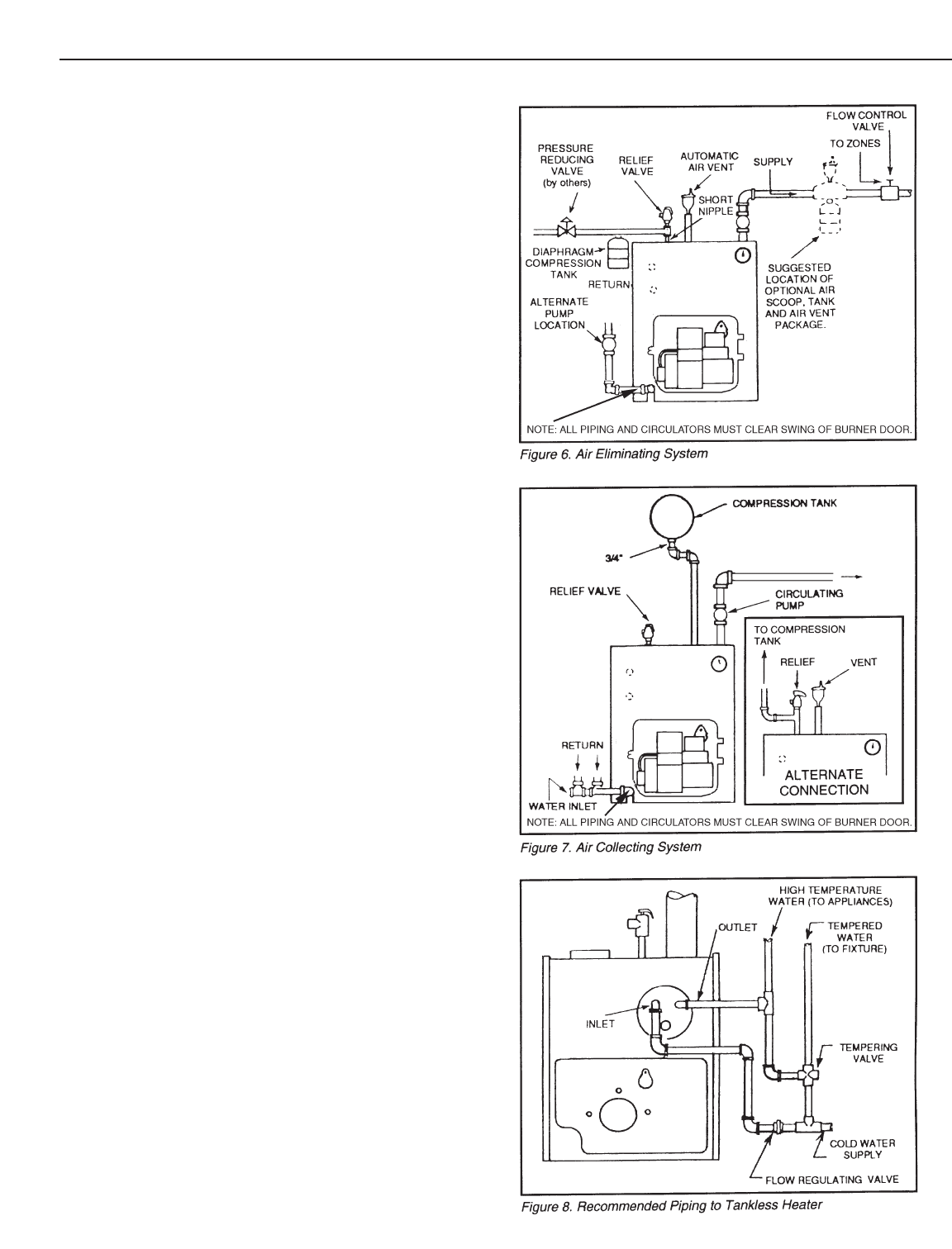
D. PUMP LOCATION-Locating low-head pump(s) on return to boil-
er is only acceptable in residences of one or two stories. (See
figure 6) The pump location shown in figure 7 is required in large,
multi-story building installations, especially when high-head
pumps are used and is also recommended for all applications.
E. A conventional compression tank may be connected to the 3/4"
tapping as shown in figure 7.
IMPORTANT: Hot water heating systems containing high water volume,
such as would occur with cast-iron radiation, require special care with air
elimination. The circulator pump should be located on the boiler supply
pipe and the expansion tank and air scoop should be located near the
pump suction.
(See Figure 6, Alternate Pump Location.)
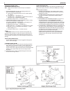
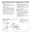
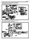
PIPING TANKLESS HEATER (if used)
I. Heater capacities are listed on Page 2.
II. Pipe the built-in tankless heater using the inlet and outlet tappings
indicated on the heater (figure 8).
A. Tempering valve (illustrated, but not furnished) is suggested to
provide more volume of temperate water to kitchen and bath.
B. High temperature water, for dishwasher and laundry, may be
piped direct.
C. A flow control valve should be used to control the rate of flow of
w
ater through the coil, otherwise the heating capacity of the coil
will be exceeded. To insure sufficient hot water, the flow rate
through the coil should be limited to a maxim
um shown for inter-
mittent draw in the ratings table on page 2.
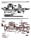
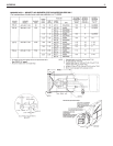
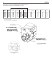
INST
ALLING THE BURNER
See Burner Data, pages 14-18, and Burner Manual supplied with burn-
er. If burner is not mounted as received, mount to boiler, placing flange
o
ver mounting studs. Use gasket between flange and boiler. Distance
between flange and nose of burner must be as shown on pages 14-18.
Check to see that nozzle and settings are as given in burner data tables,
pages 14-18.
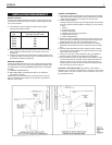
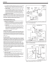
OIL SUPPLY PIPING
Install the oil tank or tanks and piping from tank to b
ur
ner. Follow local
codes and practices, NFPA No. 31, INSTALLATION OF OIL BURNING
EQUIPMENT and the instruction sheet attached to the oil burner pump.
A one-pipe system should be used for gravity-fed fuel systems and for lift
systems, where the total lift is less than 8 feet. Where the total lift is
g
reater than 8 f
eet, a tw
o-pipe system m
ust be used.
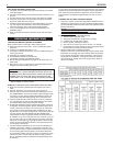
In some
instances, local codes may require a two-pipe system for below grade
fuel oil tanks. Be sure to set-up the fuel oil pump for the piping system
used;
follow the instructions attached to the pump. Be sure to include a
good quality, low pressure drop fuel oil filter in the supply line from the
tank.
This is necessary, especially at low fuel oil flow rates (small nozzle
sizes), to prevent nozzle plugging. See Slant/Fin publication on one-pipe
and two-pipe fuel oil systems.
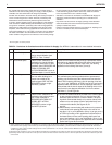
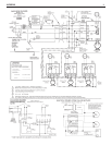
WIRING THE BOILER
A. The wiring diagrams for the burner and boiler may be found on
pages 11-13.
B. 24 volt control wiring should be approved Safety Circuit wire,
protected as needed.
C. Power supply wiring to the burner must be 14 gauge or heavier, as
required, and should ha
ve a properly fused disconnect switch. 120
volt wiring to pumps and safety controls must also be 14 gauge or
heavier. Wire must be enclosed in approved conduit.
D. All wiring must be installed in compliance with the National Electric
Code, or any local or insurance codes having jurisdiction.