


6
INTREPID
INSTALLING CONTROLS AND
ACCESSORIES ON BOILER UNITS
Note
: Jacket must be installed on boiler units prior to installation
of trim.
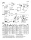
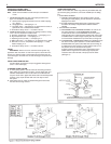
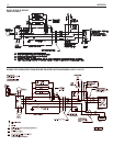
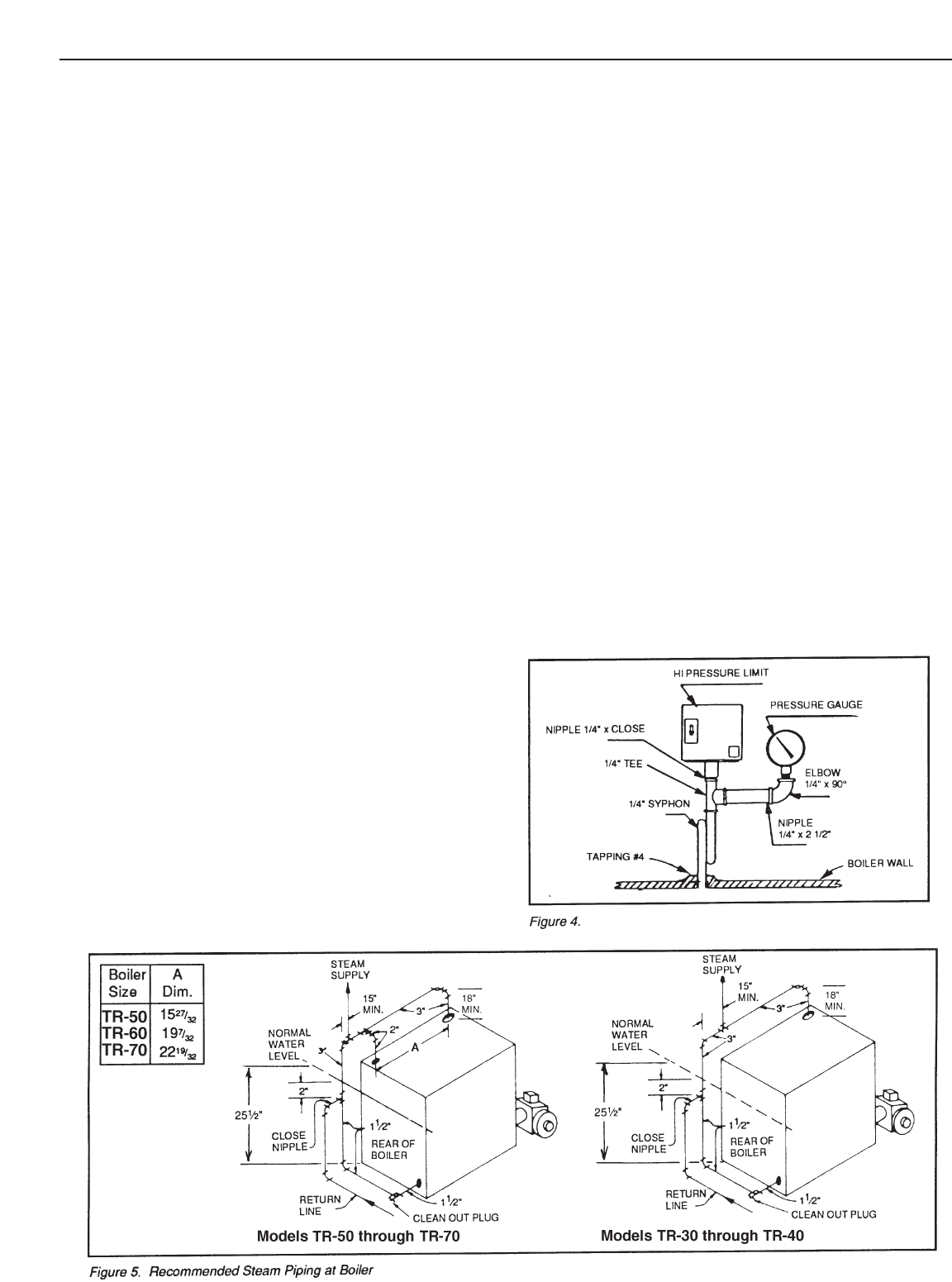
I. STEAM BOILER TRIM, see page 2 for tapping locations, and
figure 4 for illustration of steam boiler.
A. Steam pressure gauge and pressure cut-out, install in tapping
n
o. 4, figure 4.
B. Gauge glass set — use tapping no. 12.
C. Pop safety valve — use tapping no. 3, piped full size to boiler; or
pipe full size into a valveless steam header.
D. Combustion safety control — mounted on burner.
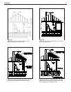
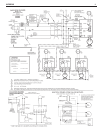
II. WATER BOILER TRIM, see page 2 for tapping locations, and fig-
ures 1 and 2 for illustration of water boiler.
A. Pressure- temperature - altitude gauge — use tapping no. 6.
B. High temperature limit — use tapping no. 7.
C. Operating control (if used) — use tapping no. 7.
D. Water relief valve — use tapping no. 3, piped full size to boiler.
E.
Automatic air vent or compression tank tappings — if used,
install in tapping no. 2.
F. Combustion safety control — mounted on burner.
PIPING
IMPORTANT:
Boilers are to be used with closed system. Any
application that uses steam or water from system, causes the intro-
duction of a frequent supply of fresh water into the boiler.This will
cause damage to the boiler. Use of heat exchangers will prevent this
damage.
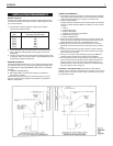
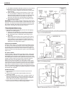
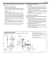
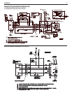
PIPING FOR STEAM BOILERS
Provide Header and Hartford Loop as suggested. See figures 4
and 5.
Local codes apply.
CLEANING PIPING SYSTEM
A. To clean piping system, open all valves at the heating elements.
After getting up a good head of steam, shut the boiler down and
allow the condensate to return to the boiler.The condensate will
carry the oil film with it. Again blow-off the boiler. On extremely fouled
systems, it may require several visits over a few days to clean
the system.
B. When steam only (no water) is released through the hand valve,
the boiler will not surge or flood.
PIPING FOR WATER UNITS
NOTE: On knocked-down boiler only, jacket may be installed after sup-
ply and return piping connection, but must be installed prior to adding
trim.
I. CIRCULATING SYSTEM
A. FORCED CIRCULATION hot water heating system: Use the
top tapping as supply tapping, and use the front or rear bottom
tappings for the return.
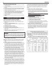
B
. A FLOW CONTROL VALVE (See figure 6) will prevent gravity
circulation and usually is required when tankless heater is
installed.
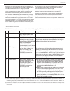
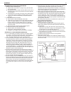
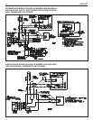
II. AIR CONTROL SYSTEMS
A. DIAPHRAGM-TYPE COMPRESSION TANKS are used to con-
trol system pressure in an AIR ELIMINATING SYSTEM:
an automatic airvent is used toREMOVE air from the system
water.See figure 6. If system pressure needs further control, add
an additional tank or install a larger capacity tank.The automatic
air vent should be installed in the top of the boiler, as in figure 6.
B. CONVENTIONAL COMPRESSION TANKS (non-diaphragm type)
are used to control system pressure in an AIR COLLECTING
SYSTEM. Within the system, after initial start-up and venting, air
is collected in the tank and acts in contact with the water to con-
trol pressure. Air is not vented from this system.
If system pressure needs further control, add another tank in
parallel with the original tank or install a large capacity tank.
Locate the tank at the inlet end of the pump near the boiler.
(See figure 7)