


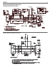


I
NTREPID
21
I. EXTENDED SHUTDOWN, CLEANING OR REMOVAL OF BOILER
FROM SERVICE.
DANGER: Use CAUTION when handling chemicals and draining hot
water from a boiler. Scalding water and/or chemicals can cause per-
manent injury to the skin, eyes and respiratory system.
A. Shut down burner by disconnecting all electrical power to the
burner by turning OFF the BURNER EMERGENCY SWITCH of
this boiler. After shutting down burner, while the boiler is still hot
(180°F to 200°F), drain water from the bottom of the boiler until it
runs clear.
B. Provide corrosion protection conditioning to the boiler water in the
heating system.There are a number of commercial heating sys-
tem preparations available from your distributor. Follow the prepa-
ration manufacturer’s instructions.
1. For steam boilers, maintain a sodium chromate solution
strength of 16 oz. per 50 gallons of water; and refill to the top
of the gauge glass.
2. For water boilers, maintain a sodium chromate solution
strength of 6 oz. per 50 gallons of water, and refill to normal
fill-pressure with system vented.
3. Raise water temperature to at least 180°F. for one hour to
release dissolved gases.
4. Shut down burner by disconnecting the main switch.
C. To clean the fireside boiler surfaces, first shut down burner by dis-
connecting all electrical power to the burner by turning OFF the
OIL BURNER EMERGENCY SWITCH of this boiler in order to
perform the following work in (1) through (10) below.
1. Remove the flue pipe from the boiler flue collar and clean
thoroughly.
2. Inspect the entire vent connector back to the chimney and
clean if necessary.
3. Inspect the chimney for soot, debris and other unsafe condi-
tions of the chimney and take the necessary action.
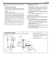
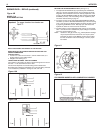
4. Remove the flue collector by first removing the top jacket
panel.The flue collector is held in place by two hex 1/4-20
screws. Remove the screws and carefully remove the flue col-
lector
.Try not to disturb the flat fiberglass rope under the flue
collector
.
5. When necessary to clean the combustion chamber you must
first CLOSE the suction valve (and return valve if two pipe).
Then disconnect the oil lines from the b
urner.The flexible
electr
ic conduit connected from the junction box on the boiler
to the burner via a plastic connector must be disconnected
from the burner by grasping the plastic half of the connector
closest to the fle
xible conduit and gently pulling it in the direc-
tion of the conduit until it is disconnected.
Remove the single
3/8-16 he
x head scre
w on the LEFT side of the s
winging door.
You will need a 9/16” drive socket. Open the door to complete-
ly expose the combustion chamber for thorough cleaning and
for inspection of target wall, blanket (provided in certain mod-
els; see rating plate), main cast iron burner door insulation
and burner door fiberglass sealing rope. If combustion cham-
ber parts above are badly deteriorated then replace with origi-
nal factory parts available at your distributor.
6. Use the flue brush to clean the pinned flueways between the
sections.† A wire brush may be used to remove any carbon
accumulation that may have developed in the combustion
chamber.Vacuum the loose soot and debris from the boiler.
7. Inspect the burner combustion head. Clean if necessary and
make sure all the adjustments are correct. (See burner data
pages for the b
urner installed.) Replace oil nozzle with new
one and readjust electrodes.To insure proper burner opera-
tion ONLY THE NOZZLES SPECIFIED IN THIS MANUAL OR
ON THE BURNER LABEL SHOULD BE USED FOR
REPLACEMENT.
8. Close main cast iron b
urner door (door on which burner is
mounted). Make sure that the entire seal (fiberglass rope) is
making good contact with the boiler casting when replacing
3/8-16 x 1” long hex head bolt and tightening.
9. Check the flue collector seal.This is the flat rope seal on top of the
heat exchanger. The rope must be in place adjacent to the long boss-
es on front and rear sections and adjacent to the short bosses on the
intermediate sections. The rope should be directly under the flue col-
lector flanges when the flue collector is replaced. Use the two 1/4-20
x 3/4” washer hex head screws to fasten the flue collector. In order to
assure a proper seal be sure that the flue collector is compressing
the flat rope and not hanging up on the section bosses.Tighten the
two screws.
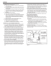
D. If boiler room is damp, provide ventilation.
II. PROVIDING PROTECTION FOR FREEZING
Anti-freeze is sometimes used in hydronic heating systems to pro-
tect against freeze-up in the event of power failure, or safety control
shutdown when the building is unoccupied. It should be recognized
that unless the building is kept above freezing temperature by some
means, the plumbing system is not protected.
PROPYLENE GLYCOL is used in the quick-freeze food industry; it is
pr
actically non-toxic. Its use may be permitted when tankless heaters
are used. When anti-freeze must be used, inhibited propylene glycol
is recommended. Useful information on the characteristics, mixing
proportions, etc. of glycol in heating systems is given in Technical
Topics No. 2A, available from the Hydronics Institute, 35 Russo
Place, Berkeley Heights, N.J. 07922. Consult glycol manufacturers
for sources of propylene glycol. DO NOT use ethylene glycol
because it is to
xic.
III.
OIL BURNER
Inspect and clean annually and following any period of improper
operation. Recheck and adjust settings as specified for burner model
and nozzle size. Set burner air and draft regulator, using test instru-
ments to obtain recommended CO
2
and draft without smoke.
Ref
er to page 8.
IV
. GENERAL MAINTENANCE
These operations are recommended to be performed at regular
inter
vals:
A.
BOILER HEATING SURFACES: clean off all coatings found.
Reseal covers.
B. BOILER CONTROLS: check contacts, settings, correct
functioning.
C
. PIPING: check piping and accessories for leaks.
D
.
CHIMNEY or STUB
VENT and BREECHING:
check for obstruc-
tions and leaks.
E. COMBUSTION AIR TO BURNER: check for continued POSITIVE
supply of air as required.
Air needs are greatest in coldest
w
eather
.
Refer to AIR SUPPLY, page 3.
F
. WATER SYSTEM: check
1. System to be full of water and pressure to remain stable
(betw
een 12 psi and 25 psi).
2. Air-control system: noise and air binding in radiation should
not occur.
3. Water lines: slightest leaks should be corrected.
4. Low water cut-off, for operation (see instructions furnished
with unit). See page 9.
G.STEAM SYSTEM: check
1.
Lo
w w
ater cut-off, for operation (see instructions furnished
with unit). See page 9.
2. Check pressure cut-off for operation. See page 10.
3. Any unusual water conditions. Obtain water analysis and treat
water.
H.BOILER ROOM AIR SUPPLY: air vents should be open and free
of obstruction. See page 3.
†
A flue brush (2-1/4" dia.) is supplied with boiler. Replacements
are available from dealer or hardware stores.
C
ARE AND MAINTENANCE