


PAGE 4
INSTALLATION INSTRUCTIONS CEILING BRACKET AN-CM270
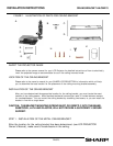
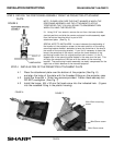
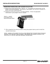
1.1 a. Select straddle beam or single beam installation.
b. Use the ceiling bracket as a template to mark the location where the pilot holes
should be drilled.
c. Drill the pilot holes for the support screws using a 1/8” drill bit into the center of
the beam. (See Figs. 2 and 3).
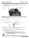
1.2 Screw the ceiling plate to the beams. Use at least 6 screws and metal washers
supplied with the unit. These screws should be tightened firmly to insure a
vibration-free support. (See Figs. 2 and 3).
Two sizes of hex head lag bolts are provided. Use shorter screws for sheet rock
surfaces and use the longer screws if the ceiling surface is constructed of a wood
lath and plaster.
CAUTION: THE BRACKET MOUNTING SCREWS MUST GO DIRECTLY INTO
THE BEAMS. SHEETROCK OR LATH AND PLASTER WILL NOT PROVIDE A
SUFFICIENTLY SECURE SUPPORT.
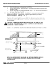
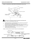
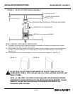
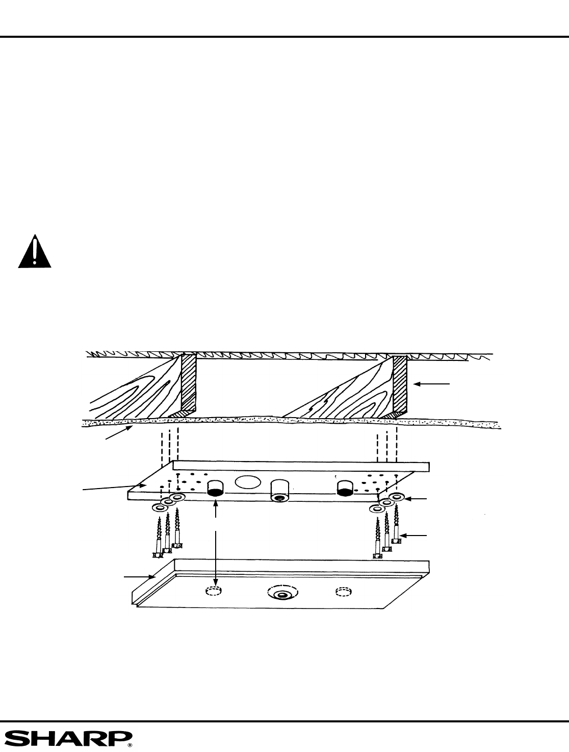
FIGURE 2. ILLUSTRATION OF STRADDLE BEAM CEILING BRACKET INSTALLATION
NOTE: THE OUTER ROW OF HOLES ARE 16” BETWEEN CENTERS WHICH IS
THE MOST COMMON BEAM SPACING IN RESIDENTIAL WOOD FRAME
CONSTRUCTION.
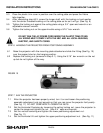
Velcro
Ceiling Mounting
Bracket
Ceiling Beam
Sheetrock or lath
and plaster ceiling
Plastic Ceiling
Bracket Trim Cover
Washers
1/4 X 10 Lag Bolt