


Digital Access Keypad Manual
SECO-LARM U.S.A., Inc.
Digital Access Keypad Manual
(+) (--)
12-24V AC/DC
Output #1
N.C. COM N.O.
Output #2
N.C. COM N.O.
Egress
In
Keypad
Active
Duress
Output
(--)
Ground
Door
Sensor
Interlock
Tamper
N.C.
O/P 1
Inhibit
12~24V
AC/DC
power
supply
+
--
Electric
Lock #1
N.O.
+
--
N.C.
N.O.
OR
ST-UV12-S1.0Q
1N4004
Egress button
(
Open door #1
from inside)
(+) (--)
12-24V AC/DC
Output #1
N.C. COM N.O.
Output #2
N.C. COM N.O.
Egress
In
Keypad
Active
Duress
Output
(--)
Ground
Door
Sensor
Interlock
Tamper
N.C.
O/P 1
Inhibit
Door #1
sensing
N.C.
N.C.
SM-200
ST-UV12-S1.0Q
SM-20
0
Cathode Cathode
12~24V
AC/DC
power
supply
+
--
Electric
Lock #2
N.O.
+
--
N.C.
N.O.
OR
1N4004
Egress button
(Open door #2
from inside)
Door #
2
sensin
g
Common ground
Cross wire connection for interlock functions
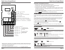
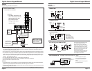
Note:
PLEASE ALSO REFER TO THE NOTES ON PAGE 6 FOR MORE GENERAL INFORMATION.
• The electromagnetic or electric door lock operation is the same as page 6.
• Relay output #2 controls the arm/disarm of the alarm control panel. Consult the alarm control panel manual for more
information.
• Connect the duress output to a 24-hour N.O. zone and the tamper output to a 24-hour N.C. zone on the alarm control
panel.
• The keypad's terminal ground (-) connects to the ground (-) wire of the alarm control panel to enable the two to work
together.
WIRING:
Example Wiring, with Connection to Lock Device and Alarm Arm/Disarm
Interlock
--
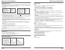
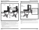
Each keypad can be used as a stand-alone keypad. The mantrap feature is for a protected area with
two doors to ensure only one door is open at a time. With the mantrap feature, when a user keys in the code to
open one door, a signal is sent to the second keypad to disable it, thereby preventing access through the second
door until the first door is closed.
Note: PLEASE ALSO REFER TO THE NOTES ON PAGE 6 FOR MORE GENERAL INFORMATION.
• Use an N.C. magnetic contact or some other N.C. device to detect whether a door is opened or closed. Do this
for the two entrances to the protected premises.
• Combine this wiring diagram with the diagram on page 7 if connection to an alarm control panel is required.
• Connect output #2 to relay output #1 disable as shown on page 6 if inhibit control is required.
• To use the mantrap feature:
o Use either the keypad from outside or the egress button from inside the protected premises to open one of
the two doors.
o While the first door is opened, the first keypad sends a signal to the second keypad to prevent the second
keypad from being used to open the second door.
o After the first door is closed, both keypads are ready to use.
DOOR #1 DOOR #2
WIRING:
Example Wiring, 2 Keypads with Mantrap
Cathode
12~24V
AC/DC
power
supply
+
--
Electric
Lock
N.O.
+
--
N.C.
N.O.
OR
N.O.
-------------
--------
--------
--------
ST-UV12-S1.0Q
1N4004
Egress button
(Inside premises)
Additional egress
buttons can be
connected in parallel
(+) (--)
12-24V AC/DC
Output #1
N.C. COM N.O.
Output #2
N.C. COM N.O.
Egress
In
Keypad
Active
Duress
Output
(--)
Ground
Door
Sensor
Interlock
Tamper
N.C.
O/P 1
Inhibit
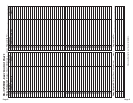
REMARKS
Output relay #1
N.O. output for fail-secure lock
N.C. output for fail-safe lock
Duress
--
To 24-hour N.O. zone
Com gnd (--) of keypad & alarm system
Relay output #2
Alarm arm/disarm control --
Consult alarm system manual for how
to connect for N.C. or N.O. operation
Tamper
--
To a 24-hour N.C. zone
}
ALARM CONTROL PANEL
}
N.C.
(--)
N.O.
COM
N.O.
N.C.
Page 10 Page 7