


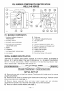
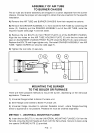
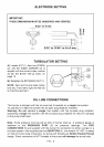
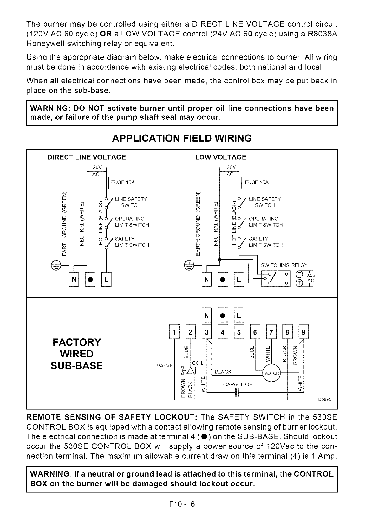
The burner may be controlled using either a DIRECT LINE VOLTAGE control circuit
(120V AC 60 cycle) OR a LOW VOLTAGE control (24V AC 60 cycle) using a R8038A
Honeywell switching relay or equivalent.
Using the appropriate diagram below, make electrical connections to burner. All wiring
must be done in accordance with existing electrical codes, both national and local.
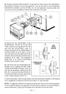
When all electrical connections have been made, the control box may be put back in
place on the sub-base.
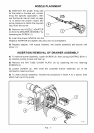
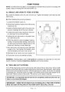
I WARNING: DO NOT activate burner until proper oil line connections have beenmade, or failure of the pump shaft seal may occur.
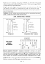
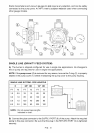
APPLICATION FIELD WIRING
DIRECT LINE VOLTAGE LOW VOLTAGE
I Eli FUSE 15A
W I _ O,/LINE SAFETY
o/ SWITCH
_1 _-_,_ / OPERATING
_1 __O/ UMiTSwITCH
/ il SAFTET_wiTCH
FUSE15A
o/ LINE SAFETY
_ F _---_'f SwiTCH
ZC_ _ _,%6/ OPERATING
OD _" __f LiMITSWiTCH
-r _ S _)/ SAFETY
1..- z ::z:/ LIMIT SWITCH
t
<
uJ
] ?WITCHING RELAY
FACTORY
WIRED
SUB-BASE
VAL
2
DI
K
_1 CAP OR
z
D5995
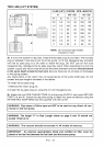
REMOTE SENSING OF SAFETY LOCKOUT: The SAFETY SWITCH in the 530SE
CONTROL BOX is equipped with a contact allowing remote sensing of burner lockout.
The electrical connection is made at terminal 4 (O) on the SUB-BASE. Should lockout
occur the 530SE CONTROL BOX will supply a power source of 120Vac to the con-
nection terminal. The maximum allowable current draw on this terminal (4) is 1 Amp.
I WARNING: If a neutral or ground lead is attached to this terminal, the CONTROLBOX on the burner will be damaged should lockout occur.
F10- 6