


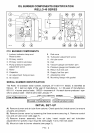
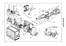
OIL BURNER COMPONENTS IDENTIFICATION
RIELLO 40 SERIES
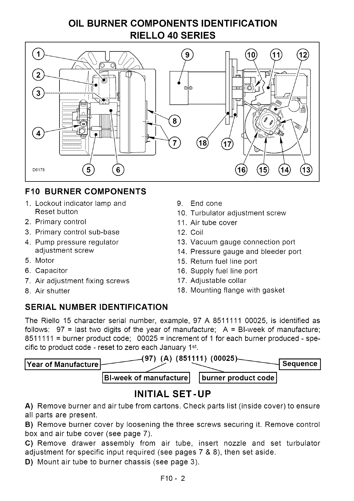
F10 BURNER COMPONENTS
1. Lockout indicator lamp and
Reset button
2. Primary control
3. Primary control sub-base
4. Pump pressure regulator
adjustment screw
5. Motor
6. Capacitor
7. Air adjustment fixing screws
8. Air shutter
9. End cone
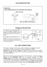
10. Turbulator adjustment screw
11. Air tube cover
12. Coil
13. Vacuum gauge connection port
14. Pressure gauge and bleeder port
15. Return fuel line port
16. Supply fuel line port
17. Adjustable collar
18. Mounting flange with gasket
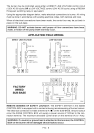
SERIAL NUMBER IDENTIFICATION
The Riello 15 character serial number, example, 97 A 8511111 00025, is identified as
follows: 97 = last two digits of the year of manufacture; A = BI-week of manufacture;
8511111 = burner product code; 00025 = increment of 1 for each burner produced - spe-
cific to product code - reset to zero each January 1st.
iYea r of Manufacture _ 97)_(A)( 851111)_ ( 00025 _ Sequence]
IBl-week of manufacture I burner product code I
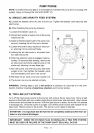
INITIAL SET-UP
A) Remove burner and air tube from cartons. Check parts list (inside cover) to ensure
all parts are present.
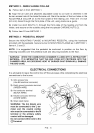
B) Remove burner cover by loosening the three screws securing it. Remove control
box and air tube cover (see page 7).
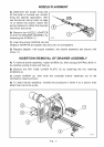
C) Remove drawer assembly from air tube, insert nozzle and set turbulator
adjustment for specific input required (see pages 7 & 8), then set aside.
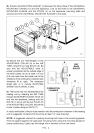
D) Mount air tube to burner chassis (see page 3).
F10- 2