


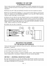
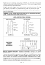
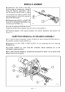
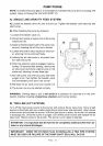
SETTING THE AIR ADJUSTMENT PLATE
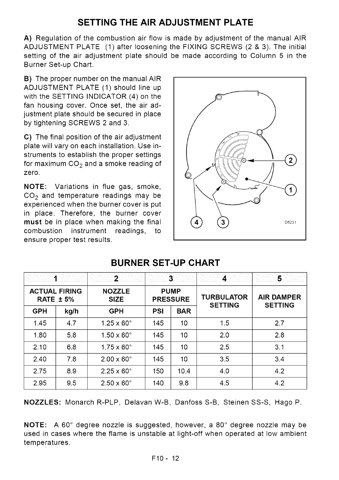
A) Regulation of the combustion air flow is made by adjustment of the manual AIR
ADJUSTMENT PLATE (1) after loosening the FIXING SCREWS (2 &3).The initial
setting of the air adjustment plate should be made according to Column 5 in the
Burner Set-up Chart.
B) The proper number on the manual AIR
ADJUSTMENT PLATE (1) should line up
with the SETTING INDICATOR (4) on the
fan housing cover. Once set, the air ad-
justment plate should be secured in place
by tightening SCREWS 2 and 3.
C) The final position of the air adjustment
plate will vary on each installation. Use in-
struments to establish the proper settings
for maximum CO 2 and a smoke reading of
zero.
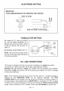
NOTE: Variations in flue gas, smoke,
CO 2 and temperature readings may be
experienced when the burner cover is put
in place. Therefore, the burner cover
must be in place when making the final
combustion instrument readings, to
ensure proper test results.
®
D5231
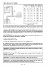
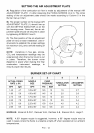
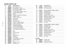
BURNER SET-UP CHART
ACTUAL FIRING
RATE + 5%
GPH
1.45
1.80
2.10
2.40
2.75
2.95
kg/h
4.7
5.8
6.8
7.8
8.9
9.5
NOZZLE
SIZE
GPH
1.25 x 60°
1.50 x 60°
1.75 x 60°
2.00 x 60 °
2.25 x 60 °
2.50 x 60 °
PUMP
PRESSURE
PSI BAR
145 10
145 10
145 10
145 10
150 10.4
140 9.8
TURBULATOR
SETTING
AIR DAMPER
SETTING
1.5 2.7
2.0 2.8
2.5 3.1
3.5 3.4
4.0 4.2
4.5 4.2
NOZZLES: Monarch R-PLP, DelavanW-B, DanfossS-B, SteinenSS-S, HagoP.
NOTE: A 60 ° degree nozzle is suggested, however, a 80 ° degree nozzle may be
used in cases where the flame is unstable at light-off when operated at low ambient
temperatures.
F10- 12