


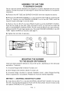
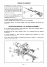
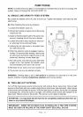
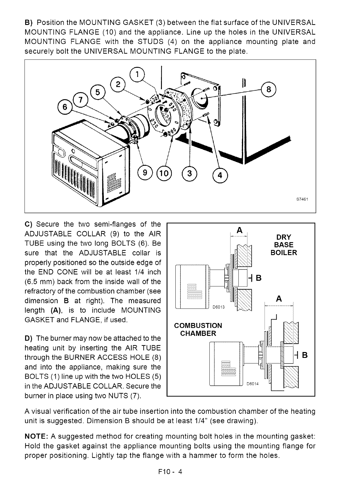
B) Position the MOUNTING GASKET (3) between the flat surface of the UNIVERSAL
MOUNTING FLANGE (10) and the appliance. Line up the holes in the UNIVERSAL
MOUNTING FLANGE with the STUDS (4) on the appliance mounting plate and
securely bolt the UNIVERSAL MOUNTING FLANGE to the plate.
$7461
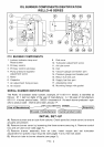
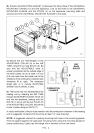
C) Secure the two semi-flanges of the
ADJUSTABLE COLLAR (9) to the AIR
TUBE using the two long BOLTS (6). Be
sure that the ADJUSTABLE collar is
properly positioned so the outside edge of
the END CONE will be at least 1/4 inch
(6.5 mm) back from the inside wall of the
refractory of the combustion chamber (see
dimension B at right). The measured
length (A), is to include MOUNTING
GASKET and FLANGE, if used.
D) The burner may now be attached to the
heating unit by inserting the AIR TUBE
through the BURNER ACCESS HOLE (8)
and into the appliance, making sure the
BOLTS (1)line up with the two HOLES (5)
in the ADJUSTABLE COLLAR. Secure the
burner in place using two NUTS (7).
iJ
D6013
COMBUSTION
CHAMBER
E::Z:Z:Z:Z:_
j .............
D6014
DRY
BASE
BOILER
A
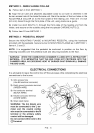
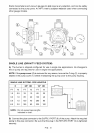
A visual verification of the air tube insertion into the combustion chamber of the heating
unit is suggested. Dimension B should be at least 1/4" (see drawing).
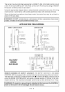
NOTE: A suggested method for creating mounting bolt holes in the mounting gasket:
Hold the gasket against the appliance mounting bolts using the mounting flange for
proper positioning. Lightly tap the flange with a hammer to form the holes.
F10- 4