


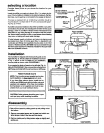
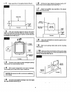
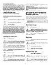

[] 11 Attachcollarand flexiblehosetocoldairplenumus-
ing(5)#8 screwsprovided.Ifaddifionaiflexiblehoseisrequiredan
eightfootlengthisavailablethroughthe partsdepartment,order
28115205.Beforeflghtening screwsinsertdamperbetweencollar
and plenum(Fig. 10). Itshouldbe openforhumidifieroperation.
___ amper Blade
(Slideshut
beforeusingair
conditioning.
Slideopenat
startof heating
season.)
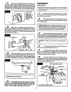
[] 12 Attach bootto humidifierusing (2) #8 screwsen-
gagedinthe tinnermannutsprovidedinbypassflange.Connect
the flexibletube as shown usingclamp provided.Do not allow
flexibletubetocome within3"offurnace fluepipebecauseofflue
pipe'sextremeheat (Fig. 11).
(5) #8 Screws #8 Screw
/
#8 : Clamp
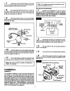
[] 13 The waste waterdrainmustbe installed.The drain
isinthe bottomofthe humidifierreservoir(Fig.12).Use 1/2" I. D.
x 10"plasflc tubing to connect drain.(Tubingissupplied.)Addi-
tionaltubing isavailableat yourSears store,Stock No. 42-3433
II
I
Ill
='q_-- Spring
°%%
L.> HoseTo
Drain
I CAUTION: Wear safetyglasses.
I
[] 14 Uaingspringhoeaclamppliem,expandhoeaclamp
andslide overen_lof_ tubingapproximately2 inches.Slide
plastictubing ontowaste water dr_n. Expandhoseclamp and
poaiUontoclamp tubingto waste waterdrain(Fig. 12).
installation
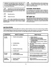
WATER SUPPLY
I CAUTION: Use plastic tubing supplied, Do not use copper
tubing because it may become disconnected when used with
hardware supplied.
[] 1 Waterforthe humidifiermustbetakenfroma nearby
coldwaterline.Turnoffthewatersupply.Drainbyopeninga fau-
cet at a lowerlevelofthe line.
[] 2 Mountthesaddlevalveonthewaterlineas closeto
the humidifieras possible.Youhavebean suppliedwith(10) feet
of 114"plastictubing.
SPECIAL NOTE: When measuring the distancefromthe
saddlevalvelocationtothehumidifier,keepinmindthatthe
tubing mustbesupported;therefore,itmustrunalongceiling
and walls.Measurealongthe paththe tubingwillfollow.
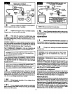
[] 3 _ outthepiercingpin bytumingthe "T" handle
counterdockwiseand thenclampthe saddlevalvebodysecurely
onthe waterlinewith rubber gasketposifionedasshown(Fig.13).
Ongalvanizedor copper pipeover5/8", firstdrilla 5/32" hole.
I AUTION: Forsafety usea handdrillor groundedelectric
drill.
[] 4 Turnhandleclockwiseuntilit haspiercedthe water
lineandvalve iscompletely closed(Fig. 13).
[] 5 Partiallyuncoilthetubing. Slidethebrasscompres-
sion nut over the tubing. The threadsin the nut mustface the
tubing end. Placethe brasscompressionsleeveas shown(Fig.
13). Slipbrassinsertintoend oftubing.
[] 6 Insert the tubing end into the saddle valve at
threaded stem"A"(Fig. 13) as far as it willgo.Threadthe brass
compression nutontothevalve,thentightengentlywith a wrench.
Takecare notto overtightenthe nut.
BrassCompressionSleeve
f BrassInsert
Brass
CompressionNut
MOUNTING SADDLEVALVE
6