


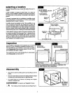
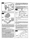

[] 8 Attachcollarand flexiblehoseto plenum.If additional
flexiblehoseis required,an eightfoot lengthis availablethrough
the partsdepartment,order281152-05. Beforetightening screws,
insert damperbetweencollarand plenum(Fig. 10). It shouldbe
open for humidifieroperation.
Damper Blade
beSlideshut
fore using air
conditioning.
Slide open at
start of heating
season.)
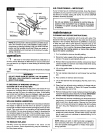
9 Connect the flexible hose as shown using clamp pro-
vided. Do not allow flexible tube to come within 3" of furnace flue
pipe because of flue pipes extreme heat. If hose is under stress
(pulling), it may be necessary to drill 2 holes in humidifier collar
for screws. This will prevent clamp from slipping off (Fig. 11).
Screws(2)
InCollar
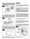
[] 10 It Is best to install an overflow line. Local codes may
require overflow protection. The overflow is in the bottom of the
humidifier reservoir (Fig. 12). Use 1/2" inside diameter rubber or
plastic tubing to connect to nearby floor drain. (Tubing not sup-
plied. Overflow tubing is available at your local hardware store.)
_ Overflow Drai_
[] 11 Installmedia wheel and reservoir trayin humidifiercase
and engage latch on right hand side to valve body inlet stem.
installation
WATER SUPPLY
[] 1 Water for the humidifier must be taken from a nearby
cold water line. Turn off the water supply. Drain by opening a fau-
cet at a lower level of the line.
[] 2 Position the saddle valve on the water line as close to
the humidifier as possible.You have been supplied with 10 feet of
1/4" plastic tubing.
SPECIAL NOTE: When measuring the distance from the
saddle valve location to the humidifier, keep in mind that the
tubing must be supported;therefore, it must runalong ceiling J
J and walls. Measure along the path the tubing will follow. I
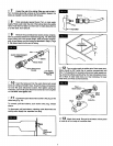
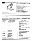
[] 3 Back out the piercing pin by turning the _ handle
counter clockwise and then clamp the saddle valve body securely
on the water line with rubber gasket positioned as shown (Fig.
13). On galvanized or copper pipe over 5/8", first ddll a 5/32' hole.
[ CAUTION: For safety,use a hand drillor groundedelectricdrill. ,J
[] 4 Turn handleclockwise until it has piercedthe water
line andvalve is completely closed (Fig. 13).
[] 5 Partially uncoil the tubing. Slide the brass compres-
sion nut over the tubing. The threads in the nut must face the
tubing end. Place the brass compression sleeve as shown in Fig.
13. Slip brass insert intoend of tubing.
[] 6 Insert the tubing end into the saddle valve at threaded
stem "A" (Fig. 13) as far as it will go.Thraad the brass compres-
sion nut onto the valve, then tighten gently with a wrench. Take
care not to overtighten the nut.
BrassCompressionSleeve
=::O/ BrassInsert
Brass
Compression Nut
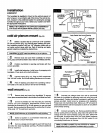
MOUNTING SADDLE VALVE
Water Pipe
UAU
Rubber Gasket
(Stem Up)
6