


Operating Instructions -
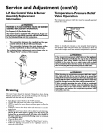
This water heater is equipped with an electrically operated vent-
ing system and a standing pilot. For the burner to come on, the
water heater thermostat must call for heat. Then the system will
begin sequencing, each section proving itself before gas is
allowed to flow to the burner.
BLOWER MOTOR
BEFORE THE WATER HEATER WILL OPERATE:
1. The control system must be connected to a 110/120 volt
power supply. The control system has an overall rating of 2
amps. The water heater must be securely and adequately
grounded in accordance with local codes and with the latest
edition of the Nationa! Electrical Code ANSI/NFPA 70.
2. The ON/OFF toggle switch, located on the control box
above the thermostat must be in the "ON" position for the
electrical control system to operate allowing the gas portion
to operate (ignite burner).
3. The pilot must be lit. See Lighting instructions on page 22
of this manual or located adjacent to the thermostat on the
water heater.
4. The gas control knob located on the thermostat must be
turned to the "ON" position for the gas to be able to flow.
5. The venting manual reset switch must be in the dosed posi-
tion. See Venting Manual Reset Switch in the For Your
Information Section".
6. There is a non-resettable hi-limit switch in the thermostat,
which must be good (dosed) for the thermostat to be o_er-
ated. See 'High Temperature Shut Off System in the For
Your Information Section".
OPERATION
When the thermostat calls for heat, gas in allowed to flow to a
(Normally open) pressure switch closing it. An electrical circuit
is then made to the blower, turning it on. The indicator light
located on the control box will come on. When the blower has
achieved sufficient venting, the airpressure switch will dose and
the indicator light will go off. A 24volt circuit will be complet-
ed through the venting manual reset switch and on to the 24
volt gas valve located just below the thermostat. The 24 volt gas
valve will open allowing gas to flow to the burner. The standing
pilot will establish a main burner flame.
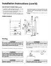
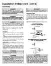
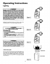
VENTING
RESET SVVITCH
DRAFT HOOD
AIR PRESSURE
ON/OFF SWITCH ,SWITCH
24V/120V
TRANSF_
GAS CONTROL
KNOB,
GAS PRESSURE
SWITCH
BURNER
GAS THERMOSTAT
THERMOCOUPLE
21