


Installation Instructions (cont'd)
_,WARNING
A gaswnt_ heater cannotoperateproperlywithout the cor-
rectamountofair forcombustion.Do notim_dlin a confined
area sucha closet,unlessyou provideair as shown in the
"Locating The New Water Heater" section.Never obstruct
theflowofventgationair.Ifyouhaveanydoubtsor questionsat
all, call your gascompany. Failure to provide the proper
amountofcombustionair canresultin afire or explosionand
cancausedeath,seriousbodilyinjury,or propertydamage.
AWARNING
If this water heater will be used in beauty shops,barber shops,
cleaning establishments, or self-service laundries with dry
deaning equipment, it is imperative that the water heater or
water heaters be installed so that combustion and vent_latlou
air be taken from outside these area_ Refer to the "Locating
The New Water Heater" sectionof this manual and also the
latest edition ofthe National Fuel Gas Code, ANSI Z223.1, also
referred to as NFPA 54 for specifics provided €oncerning air
required,
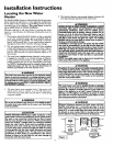
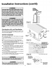
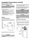
Combustion Air and Ventilation
When determining the installation location for apower vent
water heater, snow accumulation and drifting shouldbe consid-
ered in areas where applicable.
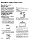
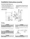
VENTING CLEARANCES
• O" clearance for 3" PVC, ABS or CPVC Schedule 40 vent piping
from combustible surfaces.
• 18" minimumin alldirections from anyobstruction that mayinter-
fere.
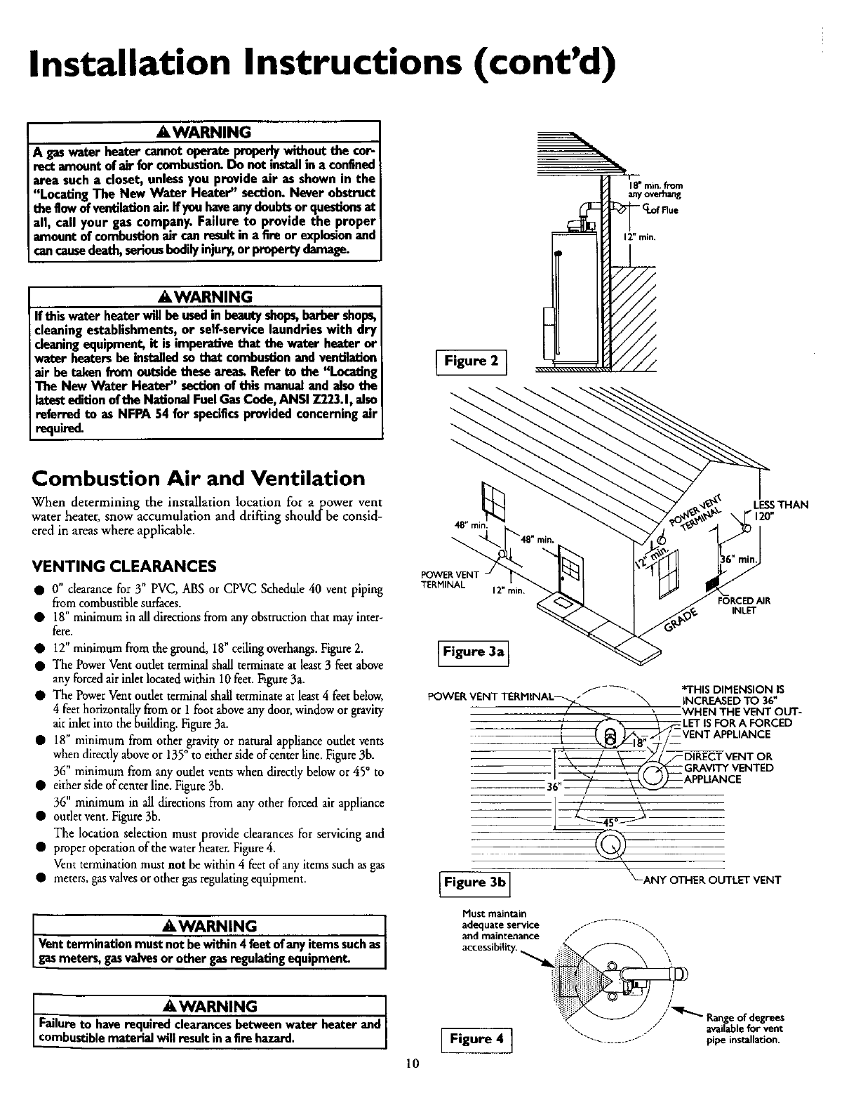
• 12" minimum from the ground, 18" ceiling overhangs.Figure2.
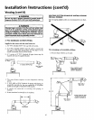
• The Power Vent oudet terminal shall terminate at least 3 feet above
any forced airinlet located within 10 feet. Figure3a.
• The Power Vent outlet terminal shall terminate at least 4 feet below,
4 feet hofizontaUy from or I foot above any door, window or gravity
air inlet into the building. Figure 3a.
• 18" minimum from other gravity or natural appliance oudet vents
• o. , , , ,
when direcdy above or 135 to either side of center hne. Figure 3b.
36" minimum from any outlet vents when directly below or 45° to
• either side of center line. Figure 3b.
36" minimum in all directions from any other forced air appliance
• outlet vent. Figure3b.
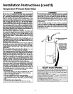
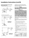
The location selection must provide clearances for servicing and
• proper operationofthewaterheater. Figure4.
Vent termination must not be within 4 feet of any items such as gas
• meters, gasvalves orothergas regulating equipment•
a_ WARNING
Vent termination must not be within 4feet of anyitems suchas
gasmeters, gasvalvesor other gasregulating equipment.
AWARNING
I Failureto have required clearances between water beater and
Lcombustible material will result in afire hazard.
Figure 2 I
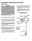
POWERVENT
TERMINAL
12" rain.
LESSTHAN
• 120"
FORCED AIR
INLET
10
Figure 3a]
f-_ *THISDIMENSIONIS
POWERVENTTERMINAL_ _ INCREASEDTO 36"
/ _ _ WHENTHEVENTOUT-
,' [_ LETISFORA FORCED
_/-- VENTAPPLIANCE
7_[ \\ / \ _/_VENTOR
GRAVITYVENTED
; i APPL,ANCE
_-ANY OTHER OUTLET VENT
I Figure 3b I
Must main_Jn
adequate service ---......... ".
arid maiRtenance ///" "',
// Rangeofdegrees
".. /" availableforvent
[ Figure 4 ] .................. pipeinstallation.