


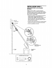
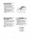
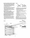
MOUNTING AND WIRING THE SAFETY SENSORS
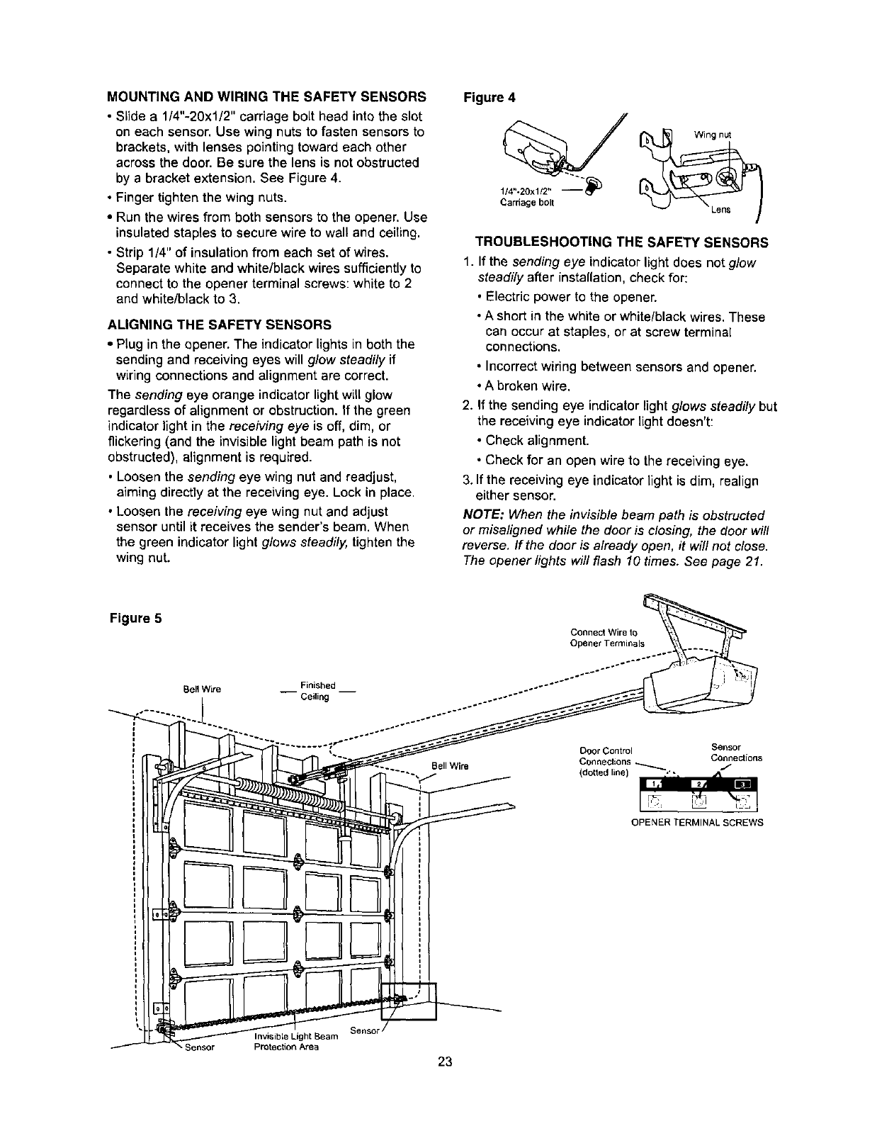
• Slide a 1/4"-20x1/2" carriage bolt head into the slot
on each sensor. Use wing nuts to fasten sensors to
brackets, with lenses pointing toward each other
across the door. Be sure the lens is not obstructed
by a bracket extension. See Figure 4.
• Finger tighten the wing nuts.
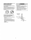
• Run the wires from both sensors to the opener. Use
insulated staples to secure wire to wall and ceiTing.
• Strip 1/4" of insulation from each set of wires.
Separate white and white/black wires sufficiently to
connect to the opener terminal screws: white to 2
and white/black to 3.
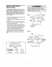
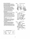
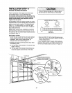
ALIGNING THE SAFETY SENSORS
• Plug in the opener. The indicator lights in both the
sending and receiving eyes will glow steadily if
wiring connections and alignment are correct.
The sending eye orange indicator light will glow
regardless of alignment or obstruction. If the green
indicator light in the receiving eye is off, dim, or
flickering (and the invisible light beam path is not
obstructed), alignment is required.
• Loosen the sending eye wing nut and readjust,
aiming directly at the receiving eye. Lock in place.
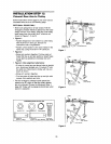
• Loosen the receiving eye wing nut and adjust
sensor until itreceives the sender's beam. When
the green indicator light glows steadily, tighten the
wing nut.
Figure 4
114"-20xl/2" _
Cardage bolt
Wing nut
TROUBLESHOOTING THE SAFETY SENSORS
1. Ifthe sending eye indicatorlightdoes not g/ow
steadily after installation, check for:
• Electricpower to the opener.
• A short in the white or white/blackwires. These
can occur at staples, or at screw terminal
connections.
• Incorrectwiring between sensors and opener.
• A broken wire.
2. If the sending eye indicatorlightg/ows steadily but
the receivingeye indicatorlight doesn't:
• Check alignment.
• Check for an open wire to the receiving eye.
3. If the receivingeye indicatorlight is dim, realign
either sensor.
NOTE: When the invisib/ebeam path is obstructed
or misa/igned while the dooris c/osing, the door wi//
reverse. /f the door is a/ready open, it wi//not dose.
The opener /ights willflash 10 times. See page 21.
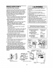
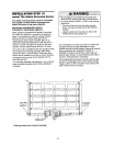
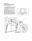
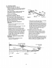
Figure 5
Connect Wire to
Opener Terminals
Bell Wire __ Finished __
Ceiling
Bell Wire
Door Control Sensor
Connections _ Connections
(dotted line) .'- J
%
OPENER TERMINAL SCREWS
Sellsot"
Invisible Light Seam
Protection Area
23