


INSTALLATION STEP 6
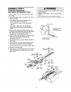
Install the Door Control
Locate door control within sight of door, at a minimum
height of 5 feet where small children cannot reach,
away from moving parts of door and door hardware.
If installing into drywall, drill 5/32" holes and use the
anchors provided. For pre-wired installations (as in
new home construction), it may be mounted to a
single gang box (Figure 2).
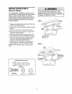
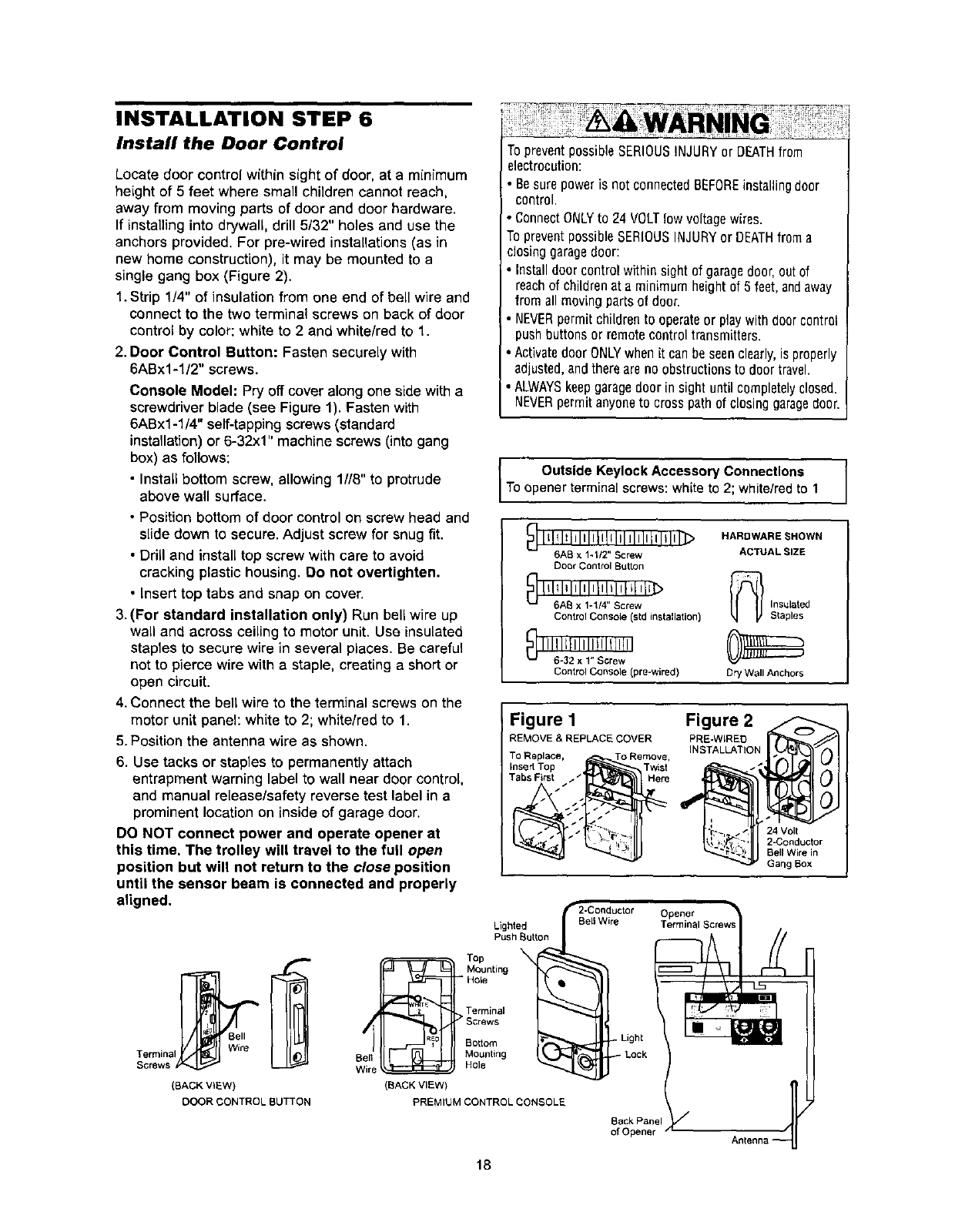
1. Strip 1/4" of insulation from one end of bell wire and
connect to the two terminal screws on back of door
control by color: white to 2 and white/red to 1.
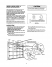
2. Door Control Button: Fasten securely with
6ABx1-l/2" screws.
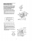
Console Model: Pry offcover along one side witha
screwdriver blade (see Figure 1). Fasten with
6ABx1-1/4" self-tapping screws (standard
installation) or 6-32x1" machine screws (into gang
box) as follows:
• Install bottom screw, allowing 1//8" to protrude
above wall surface.
• Position bottom of door control on screw head and
slide down to secure. Adjust screw for snug fit.
• Drill and install top screw with care to avoid
cracking plastic housing. 13onot overtighten.
• Insert top tabs and snap on cover.
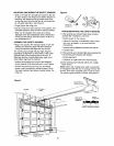
3. (For standard installation only) Run bell wire up
wall and across ceiling to motor unit. Use insulated
staples to secure wire in several places. Be careful
not to pierce wire with a staple, creating a short or
open circuit.
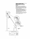
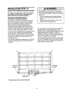
4. Connect the bell wire to the terminal screws on the
motor unit panel: white to 2; white/red to 1.
5. Position the antenna wire as shown.
6. Use tacks or staples to permanently attach
entrapment warning label to wall near door control,
and manual release/safety reverse test label in a
prominent location on inside of garage door.
DO NOT connect power and operate opener at
this time, The trolley will travel to the full open
position but will not return to the close position
until the sensor beam is connected and properly
aligned.
TopreventpossibleSERIOUSINJURYor DEATHfrom
electrocution:
• Besurepoweris not connectedBEFOREinstallingdoor
control.
• ConnectONLYto24 VOLTlow voltagewires.
TopreventpossibleSERIOUSINJURYor DEATHfroma
closinggaragedoor:
• Installdoorcontrolwithinsightofgaragedoor,out of
reachof childrenat aminimumheightof5feet,andaway
fromall movingpartsofdoor.
• NEVERpermitchildrento operateor playwithdoorc0ntrol
pushbuttonsor remotecontroltransmitters.
• ActivatedoorONLYwhenitcanbeseenclearly,is properly
adjusted,andthereareno obstructionstodoortravel.
ALWAYSkeepgaragedoor insight untilcompletelyclosed.
NEVERpermitanyoneto crosspathof closinggaragedoor.
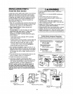
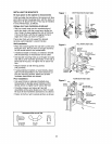
Outside Keylock Accessory Connections
To opener terminal screws: white to 2; white/red to 1
_] I_!ll_illlllliltltl Illliillllil_>
6AB x 1-1/2" Screw
Door Control Button
H; IAI212Il1111/12,,tiSIcl'el/VJ_
Control Console (std installation)
I 116!; I21IxII,!': Ictrle!;II
Control Console (pre-wired)
HARDWARE SHOWN
ACTUAL SIZE
_ nsulated
Staples
Dry Wall Anchors
Figure 1
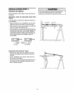
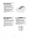
REMOVE & REPLACE COVER
TO Replace, To Remove,
Insert Top Twist
Tabs First__._._. Here
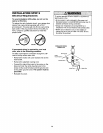
Figure 2
PRE-WtRED
INSTALLATION
24 Volt
2-Conductor
BellWire in
Gang Box
Lighted
Push Button
Bell
Terminal Wire
Screws
(BACK V_EW)
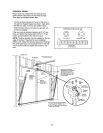
DOOR CONTROL BUTTON
:_F==_===_== Top
_v Mounting
- Hole
. > Terminal
/ _ Sorews
Bottom
Ben Mounting
Wire _ Hole
(BACK VIEW)
PREMIUM CONTROL CONSOLE
Back Panel
of Opener
18