


Installation Step 6
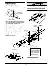
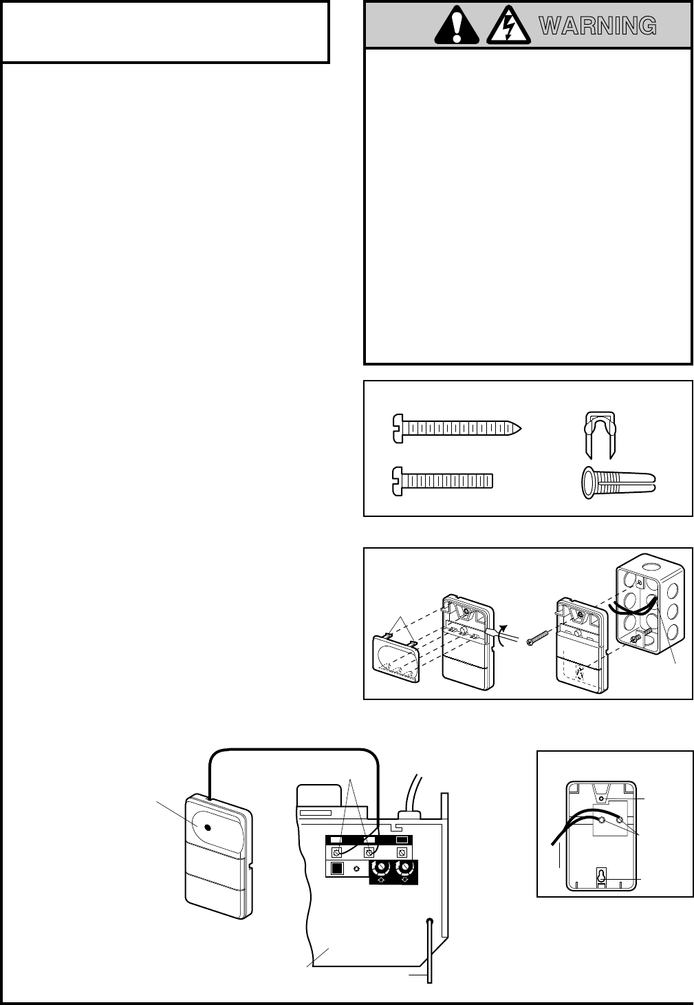
Install the Door Control
18
Do not connect to live electrical wiring. Connect
only to 24 Volt low voltage wires. Connection to
live wires or higher voltage may cause serious
injury from shock, burn or electrocution.
Children operating or playing with a garage
door opener can injure themselves or others.
The garage door could close and cause
serious injury or death.
Install the door control (or any additional push
buttons) out of the reach of children and away
from all moving parts of the door and door
hardware,
but where the garage door is visible.
Do not allow children to operate the push
button(s) or the remote control(s).
A moving garage door could injure someone
under it.
Activate the opener only when the
door is properly adjusted, you can see it
clearly, and there are no obstructions to door
travel.
WARNING
CAUTION
WARNING
AVERTISSEMENT
ATTENTION
AVERTISSEMENT
WARNING
AVERTISSEMENT
Sears
DoorContrl front/back
7/95
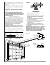
Lighted
Push Button
Antenna
Back Panel
of Opener
Opener
Terminal Screws
KG
KG
1
3
9
7
5
1
3
9
7
5
2 3
1
2-Conductor
Bell Wire
STANDARD
CONTROL
CONSOLE
Bouton-poussoir
éclairé
Antenne
Panneau arrière
de l'ouvre-porte
Bornes filetées
de 2 conducteurs
KG
KG
1
3
9
7
5
1
3
9
7
5
2 3
1
Fil de sonnerie à
2 conducteurs
COMMANDE
MURALE
STANDARD
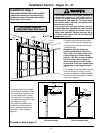
Dry Wall Anchors
Insulated
Staples
6AB x 1-1/4" Screw
Control Console (std installation)
6-32 x 1" Screw
Control Console (pre-wired)
6AB x 1-1/2" Screw
Door Control Button
Chevilles pour murs secs
Agrafe
isolée
Vis 6ABx1-1/4 po Commande murale
(pour installation standard)
Vis 6-32x1 po Commande murale
(pour installation pré-câblée)
Vis 6ABx1-1/2po
Bouton de commande
Hardware Shown Actual Size
The Chamberlain Group, Inc.
Std Console Door Control
8/95
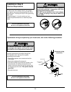
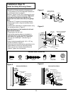
To Replace,
Insert
Top Tabs
First
To Remove,
Twist
Here
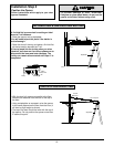
PRE-WIRED
INSTALLATION
REMOVE & REPLACE COVER
Figure 1 Figure 2
24 Volt
2-Conductor
Bell Wire
Pour remettre,
insérer tout d'abord
les pattes
supérieures
Pour enlever,
dévisser à
cet endroit
INSTALLATION
PRÉ-CÂBLÉE
POUR ENLEVER ET REMETTRE
LE COUVERCLE
Figure 1 Figure 2
Fil de sonnerie
24 V à
2 Conducteurs
Sears
DoorContrls/RearView
7/95
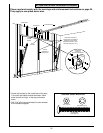
Bell
Wire
Terminal
Screws
STANDARD CONTROL
(BACK VIEW)
Top
Mounting
Hole
Bottom
Mounting
Hole
WHITE
2
RED
1
Bornes
filetées
TÉlÉCOMMANDE STANDARD
(VUE ARRIÈRE)
Trou de
fixation
supérieur
Trou de
fixation
inférieur
BLANC
2
ROUGE
1
Fil de
sonnerie
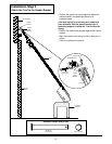
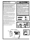
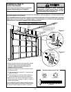
Locate the door control within sight of the door
at a minimum height of 5 feet where small
children cannot reach, and away from all moving
parts of the door and door hardware.
The door control is typically attached directly to the
wall. If installing into drywall, drill 5/32" holes and use
the anchors provided.
For pre-wired installations (as
in new home construction), Console models may be
mounted to a standard single gang box (Figure 2).
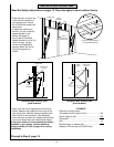
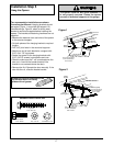
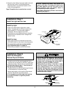
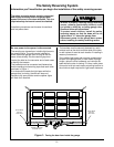
1.Strip 1/4" of insulation from one end of the bell
wire and connect it to the two screw terminals on
the back of the door control: white to 2, and
white/red to 1.
2.Pry off cover along one side with a screwdriver
blade (see Figure 1). Fasten with 6ABx1-1/4” self-
tapping screws (standard installation) or 6-32x1"
machine screws (pre-wired installation) as follows:
• Install bottom screw, allowing 1/8" to protrude
above wall surface.
• Position bottom of door control on screw head and
slide down to secure. Adjust screw for snug fit.
• Drill and install top screw with care to avoid
cracking plastic housing.
Do not overtighten.
• Insert top tabs and snap on cover.
3.
(For standard installation only)
Run the bell wire
up the wall and across the ceiling to the opener.
Use insulated staples to secure the wire in several
places. Be careful not to pierce the wire with a
staple, creating a short.
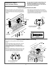
4. Connect the bell wire to the terminal screws on the
opener panel: white to 2; white/red to 1.
5. Position the antenna wire as shown.