


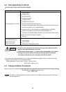

8-4-2. Inspection Points for Each Part
(1) Outdoor control circuit board
Refer to 8-3-1. Checking the outdoor unit.
(2) Fuse
Check it visually or the continuity with a tester.
(3) Compressor
Check for an open circuit in the compressor coil winding.
(4) Compressor protective sensor (compressor discharge temperature thermistor)
Check that the senseor is securely contained in the thermostart holder.
(5) 4-way valve
Short-circuit the T-RUN terminal to the COM terminal of TEST/T-RUN terminals. Perfrom a test run of the unit
alone, and check whether the 4-way valve inside the outdoor unit produces a click sound.
(6) Coil thermistor
Check that the sensor is securely contained in the thermostat holder.
Do not remove or insert the outdoor control circuit board connector when power is being supplied to it.
(The controller will be damaged.)
NOTE
No voltage on circuit board
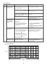
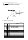
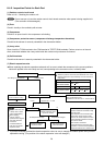
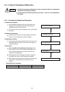
(7) Electric expansion valve
When replacing the electric expansion valve and coil, be sure to attach the connectors in the correct positions.
Labels are applied to the valve body and coil, corresponding to the connector colors, to identify them.
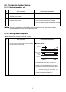
Controller check
Voltage varies
0 ohm
No temperature change Temperature changes
Replace the coil.
Open and close the
electric expansion valve
by hand to check it.
Replace the electric
expansion valve.
This part is normal.
Check elsewhere.
Check the illumination
of the red Power Lamp.
Replace the controller.
Check the coil resistance.
Use a multi-meter to measure the voltage (12 V).
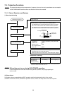
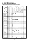
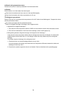
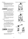
Model No. Sequence
SAP-CMRV1426EH
SAP-CMRV1926EH
SAP-CMRV2446EH
SAP-CMRV3146EH
SAP-CMRV1936EH
MV0 MV1
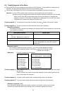
When the power is turned ON, the needle will move in the
following seguence in approximately 10 to 20 seconds for
each point.
Check the resistance between the gray lead
wire and the other wires.
Resistance is OK if it is 46 +/– 4ohm at 20 °C
Cool the main unit with
a damp cloth or other
means while welding.
When applying
vacuum, use the
special service magnet
and rotate at least 5
revolutions
counterclockwise to
fully open the electric
expansion valve.
*1
Approx. 46 +/– 4 ohm
NOTE
If you have manually checked the electric expansion valve, be sure to reapply the outdoor power after you have
replaced the wiring. (The position of the elecric expansion valve will changed.)
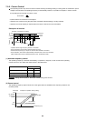
*1
MV0 MV1 MV2
MV0 MV1 MV2 MV3
Use the special service magnet and
rotate 5 revolutions clockwise to fully
close the valve.
Then start the unit and measure the
temperature at the inlet and outlet
tubes of the electric expansion valve.
If the temperature difference is large,
the valve is closed.
Then rotate 5 revolutions
counterclockwise to open the valve.
Operation is normal if the temperature
difference between the 2 tubes drops.
75