


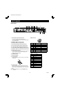
PARTS NAMES
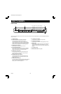
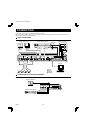
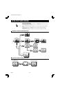
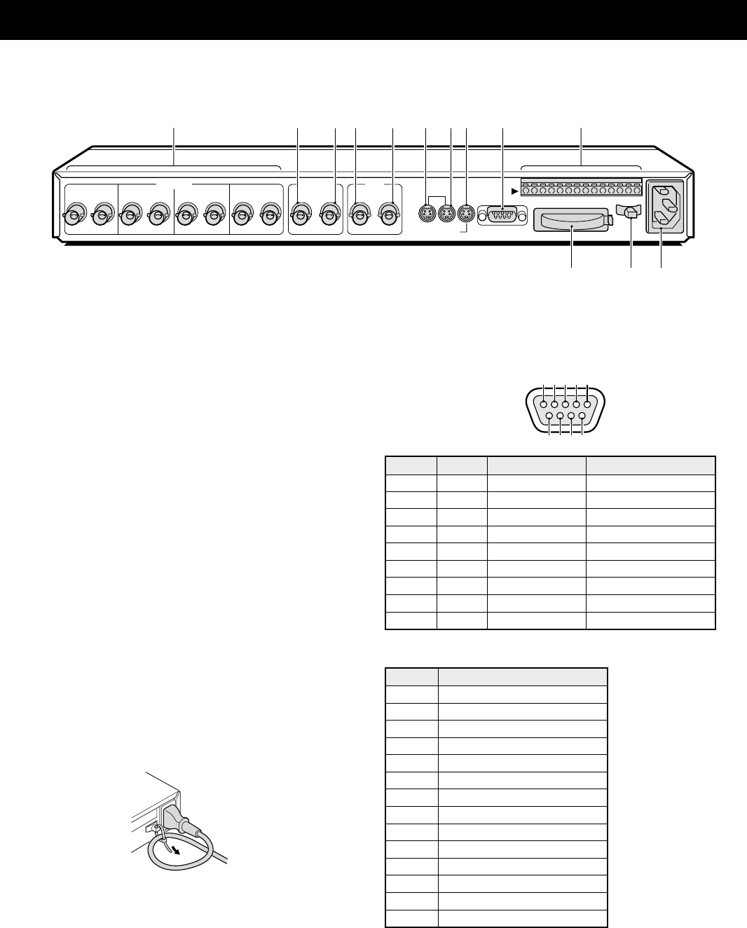
REAR PANEL
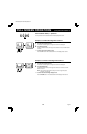
1 IN/OUT (Camera input/output) terminals
Connect the cameras cable to the IN terminals.
You can use the OUT terminal to output the camera signal
input at the IN terminal.
2 MONITOR 1 (Monitor 1 output) terminal
3 MONITOR 2 (Monitor 2 output) terminal
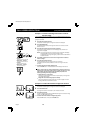
4 VCR IN (Video cassette recorder input) terminal
5 VCR OUT (Video cassette recorder output) terminal
6 S-VHS VCR IN (VCR S-VIDEO signal input) terminal
7 S-VHS VCR OUT (VCR S-VIDEO signal output) terminal
8 MONITOR 1 (Monitor 1 S-VIDEO signal output) terminal
9 RS232C (RS-232C) terminal
To control this unit using a personal computer, connect the
computer serial terminal to this terminal using a 9-pin
D-SUB cable (sold separately).
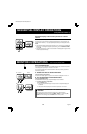
F CONTROL terminal
G Battery compartment
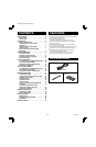
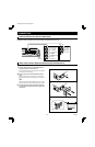
H Power cord holder
Using the supplied tie, attach the power cord to the holder
as illustrated.
I AC Power socket
Insert the power cord female plug firmly into this socket.
When the other plug of the power cord is connect to a live
power source, the POWER indicator on the front panel will
light.
NOTE: Model MPX-MD4 does not have S-VIDEO IN, OUT
terminals.
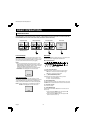
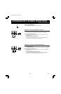
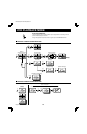
(RS232C terminal)
Pin No. Signal Function Signal direction
1 –– –
2 RXD Data reception Computer → Multiplexer
3 TXD Data transmission Multiplexer → Computer
4 –– –
5 GND Ground –
6 –– –
7 RTS Request to send Multiplexer → Computer
8 –– –
9 –– –
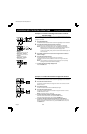
(CONTROL terminal)
Pin Signal
G Ground
C Common
R1 Remote input 1
R2 Remote input 2
C Common
S Switching input (DC 5V)
C Ground
A Alarm output (DC 5V)
C Common
1 Alarm input 1
2 Alarm input 2
3 Alarm input 3
4 Alarm input 4
C Common
1
IN OUT
2
IN OUT
3
IN OUT
4
IN OUT IN1 2 OUT
IN OUT
S-VHS
VCR
MONITOR 1 RS232C
CONTROL
GC
R1R2
CSCAC1234C
16789F
HI
CAMERA
VCR
MONITOR
2345
G
9876
54321
L8FH5/US (MPX-CD4 GB) 1999. 6. 4
4 English