


53
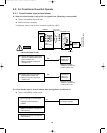
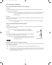
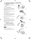
10-1. Measurement of Insulation
Resistance
● The insulation is in good condition if the resistance
exceeds 2MΩ.
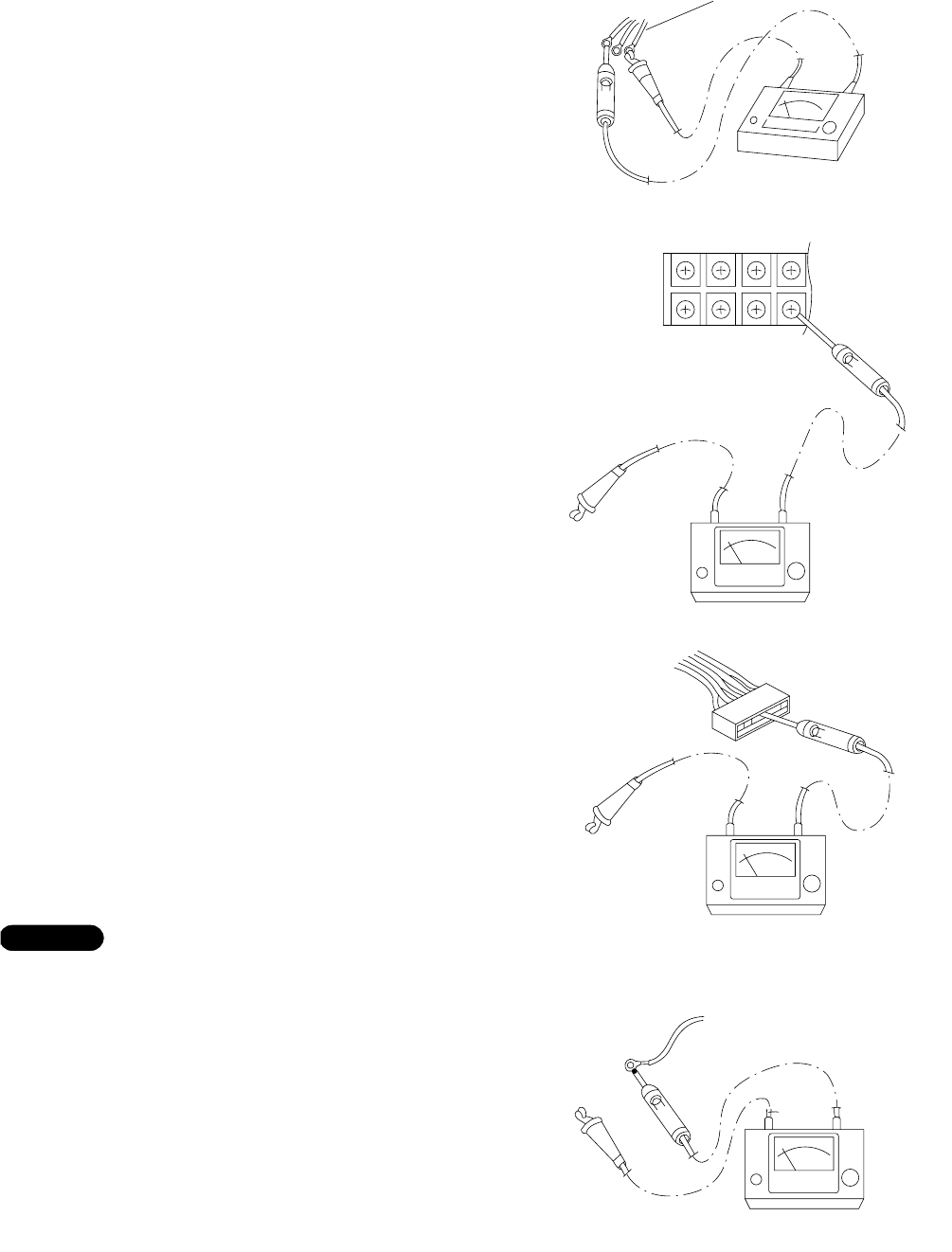
10-1-1. Power Supply Wires
Clamp the ground wire of the power supply wires with
the lead clip of the insulation resistance tester and
measure the resistance by placing a probe on either of
the power wires. (Fig. 1)
Then measure the resistance between the ground wire
and the other power wire. (Fig. 1)
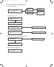
10-1-2. Indoor Unit
Clamp an aluminum plate fin or copper tube with the
lead clip of the insulation resistance tester and mea-
sure the resistance by placing a probe on each termi-
nal screw on the terminal plate. (Fig. 2)
Note that the groundline terminal should be skipped for
the check.
10-1-3. Outdoor Unit
Clamp an aluminum plate fin or copper tube with the
lead clip of the insulation resistance tester and mea-
sure the resistance by placing a probe on each termi-
nal screw where power supply lines are connected on
the terminal plate. (Fig. 2)
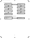
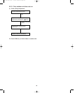
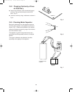
10-1-4. Measurement of Insulation
Resistance for Electrical Parts
Disconnect the lead wires of the desired electric part
from terminal plate, capacitor, etc. Similarly disconnect
the connector. Then measure the insulation resistance.
(Figs. 3 and 4)
Refer to Electric Wiring Diagram.
If the probe cannot enter the poles because the hole is
too narrow then use a probe with a thinner pin.
NOTE
Insulation
tester
Probe
Clip
Ground wire
Fig. 1
Terminal plate
Copper
tube or
metallic part
Clip
Insulation
tester
Probe
Fig. 2
Copper
tube or
metallic part
Clip
Insulation
tester
Probe
Fig. 3
Clip
Insulation
tester
Probe
Metallic
part
From fan motor,
compressor and
other parts
Fig. 4
10. CHECKING ELECTRICAL COMPONENTS
000-215 SM (1-56) 7/5/00 2:49 PM Page 53