40
7-3. Address Switches
If you are installing more than 1 indoor unit (up to 2) in
the same room, it is necessary for you to assign each
unit its own address so each can be operated by its own
remote control unit. You assign the addresses by
matching the switch positions of each indoor unit with
the switch positions of its remote control unit. The
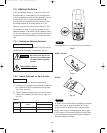
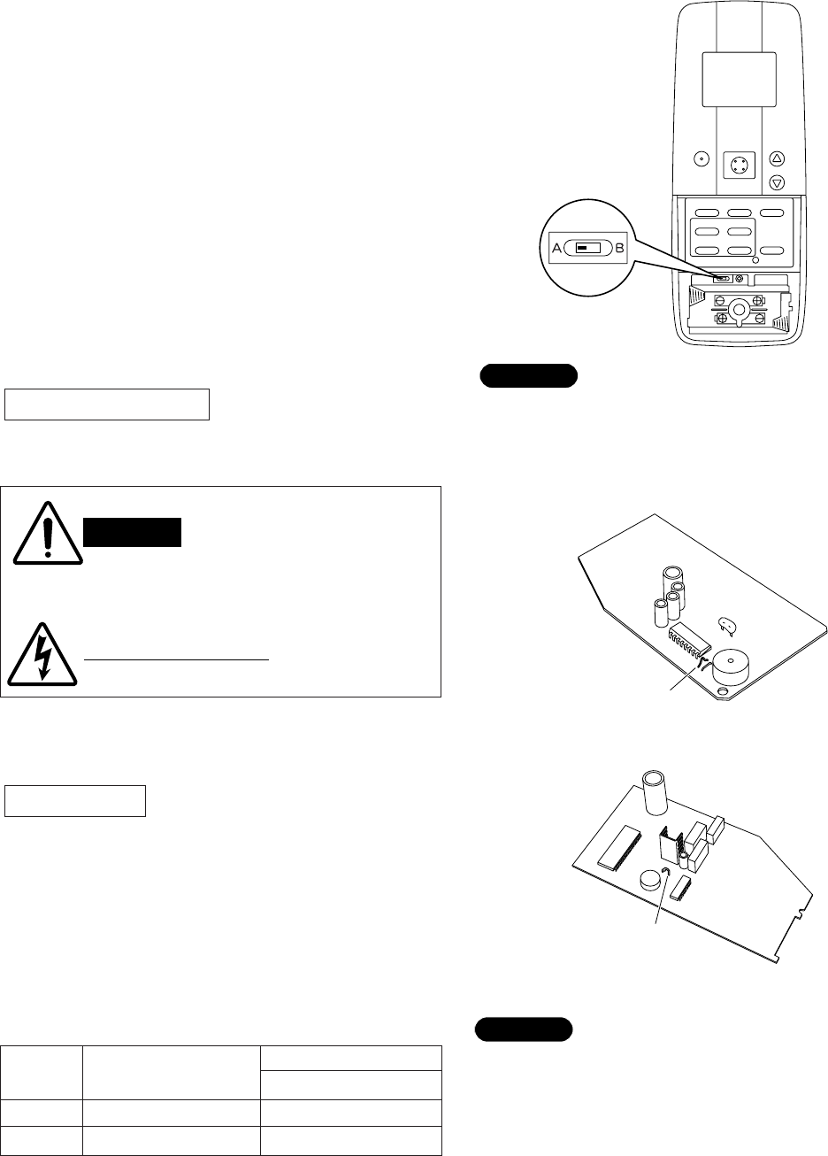
switches of the remote control unit are shown in Fig. 8.
For instance, to set up 2 indoor units, switch Unit A’s
address switches. Then switch Unit B’s address switch-
es.
It is important that you match the switches of the air
conditioner unit with the switches of its remote control
unit.
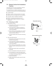
7-3-1. Finding the Address Switches
Remove the lid and unit’s 2 batteries. You can see the
switches inside the battery compartment. (Fig. 8)
7-3-2. Switch Positions for Up to 2 Units
Remove the casing, then follow the steps below.
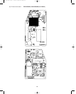
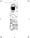
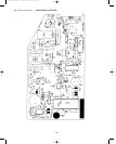
a) Unscrew the cover plate of the electrical component
box. Remove the PCB. Locate and cut the jumper
wire. (Figs. 9 and 10)
b) Table 2 shows the positions you can use for up to 2
indoor units installed in the same room. (Figs. 8, 9
and 10)
Table 2
Indoor Unit
Remote Control Unit
Address
Fig. 8
WARNING
Risk of Electric Shock
Be sure to turn the air con-
ditioner off and disconnect
the power before opening
the unit.
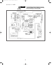
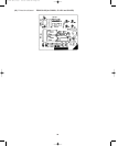
JP11
Fig. 9
JP11
Fig. 10
An indoor unit cannot be remote controlled if its remote
control unit is too far away (more than 26 ft.). If the
remote control unit does not seem to work correctly,
bring it closer to the unit being operated and try again.
For this reason, if the remote control unit is to be used
from a fixed position, operation should be checked at
that position before mounting.
NOTE
Address switch is in “A” position at time of shipment.
NOTE
Unit No.
Remote Control
Indoor Unit
Jumper Wire
Address
JP11
1 A Do not cut
2 B Cut
KS1852
KS0951, KS1251
000-215 SM (1-56) 7/5/00 2:49 PM Page 40


