


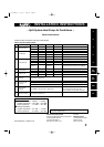

7
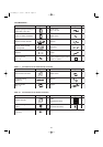
<RCS-BH80UA.WL>
7-12. Separate Type Signal Receiving Unit Installation
7-13. Electrical Wiring
7-14. Test Run Switch
7-15. Misoperation Alarm Indicators
7-16. Basic Wiring Diagram
7-17. Wiring System Diagram for Group Control
7-18. Wiring System Diagram for Multiple Remote Controllers
<RCS-SH1UA>
7-19. Test Run Procedure
7-20. Check Items Before the Test Run
7-21. Preparing for the Test Run
7-22. Precautions
7-23. When Setting Indoor Unit Control PCB Switch for
Wall-Mounted Indoor Unit
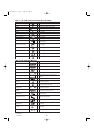
8. HOW TO INSTALL THE SYSTEM CONTROLLER
(OPTIONAL PART) . . . . . . . . . . . . . . . . . . . . . . . . . . . . . . . . . 85
8-1. System Controller Installation
8-2. Electrical Wiring
8-3. Address Switch Setting
8-4. Mode Setting
8-5. How to Perform Zone Registration
8-6. Connection with Other Equipment
8-7. Memory Back Up Switch
8-8. Test Run
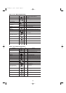
9. HOW TO PROCESS TUBING . . . . . . . . . . . . . . . . . . . . . . . . . 97
9-1. Connecting the Refrigerant Tubing
9-2. Connecting Tubing between Indoor and
Outdoor Units
9-3. Insulating the Refrigerant Tubing
9-4. Taping the Tubes
9-5. Finishing the Installation
10. LEAK TEST, EVACUATION AND ADDITIONAL
REFRIGERANT CHARGE . . . . . . . . . . . . . . . . . . . . . . . . . 101
10-1. Leak Test
10-2. Evacuation
10-3. Charging Additional Refrigerant
10-4. Finishing the Job
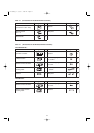
11. TEST RUN . . . . . . . . . . . . . . . . . . . . . . . . . . . . . . . . . . . . . . . 104
11-1. Preparing for Test Run
11-2. Caution
11-3. Test Run Procedure
11-4. Items to Check Before the Test Run
11-5. Test Run Using the Remote Controller
11-6. Precautions
11-7. Table of Self-Diagnostic Functions and Corrections
(X, T, U, K Type)
11-8. Examples of Wiring Diagrams
Page
07-115 SSHP_II 5/7/07 3:59 PM Page 7