


51
U
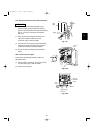
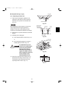
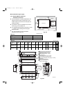
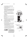
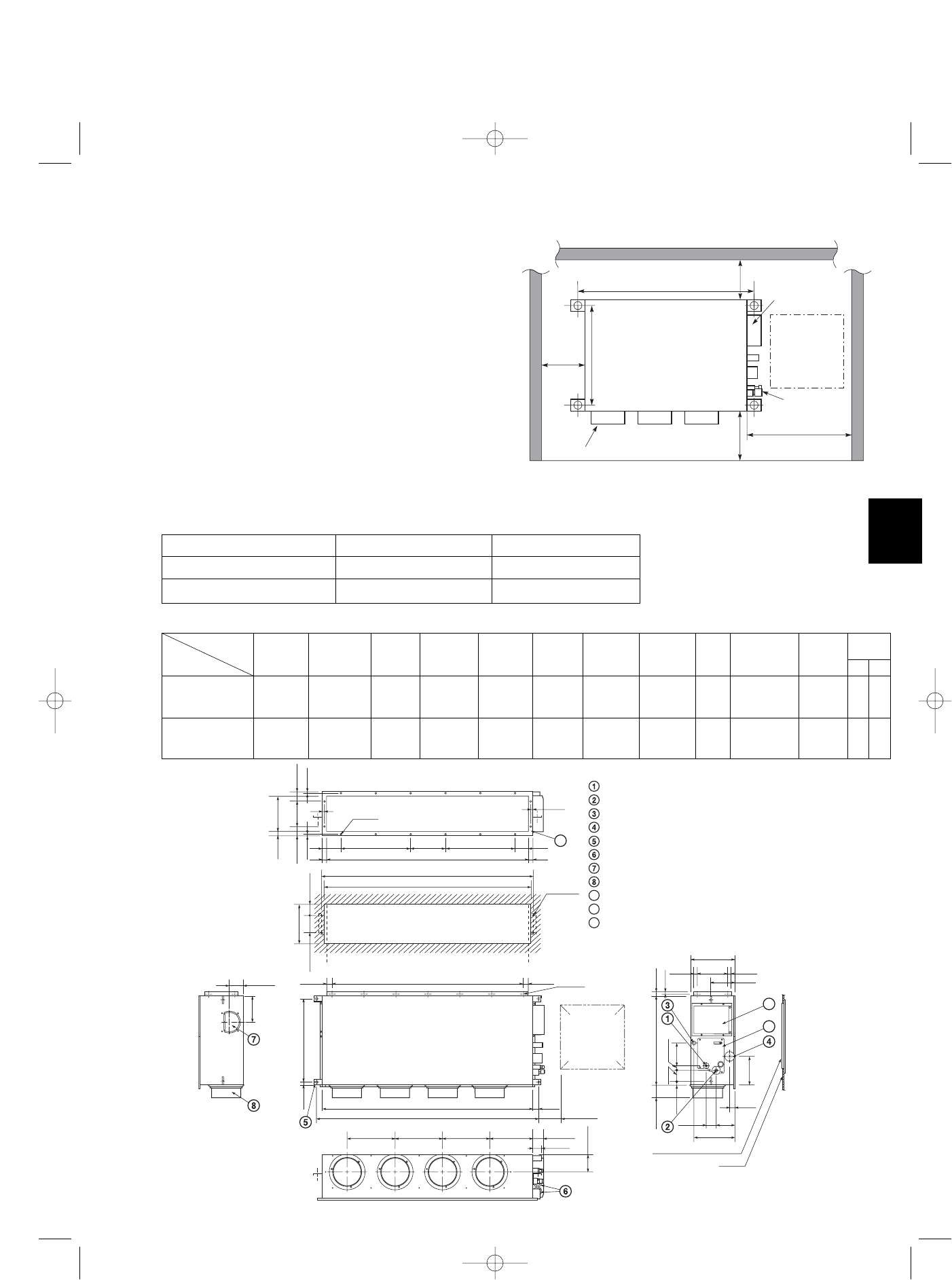
■ Concealed-Duct Type (U Type)
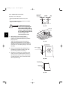
3-22. Required Minimum Space for
Installation and Service
●
This air conditioner is usually installed above the
ceiling so that the indoor unit and ducts are not
visible. Only the air intake and air outlet ports are
visible from below.
●
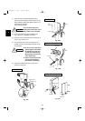
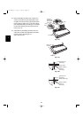
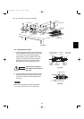
The minimum space for installation and service is
shown in Fig. 3-91 and Table 3-4.
●
It is recommended that space is provided (17-23/32
× 17-23/32 in.) for checking and servicing the
electrical system.
●
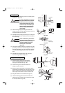
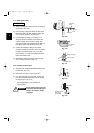
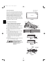
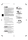
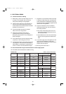
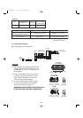
Fig. 3-92 and Table 3-5 show the detailed
dimensions of the indoor unit.
Table 3-4
Unit: inch (mm)
Type 26 36
A (Length) 42-17/32 (1,080) 61-13/32 (1,560)
Number of duct flanges 34
ABCDEFGHIJK
35-7/16 9-21/32
UH(W)2672R
37-7/8
(7-3/32×5)
39-3/8 42-17/32 11-13/32 2-23/32 38-19/32 39-31/32 5-1/8
(9-21/32×1)
9-27/32 12 16
54-11/32 19-9/32
UH(W)3672R
56-25/32
(9-1/16×6)
58-9/32 61-13/32 13-3/16 12-7/32 57-15/32 58-27/32 5-1/8
(9-21/32×2)
9-7/16 16 18
No. of
holes
Dimension
Table 3-5
Unit: inch (mm)
Refrigerant tubing joint (liquid tube)
Refrigerant tubing joint (gas tube)
Upper drain port (O.D. 1-1/4 in.)
Bottom drain port (O.D. 1-1/32 in.)
Suspension lug
Power supply outlet (2-ø1-3/16 hole)
Fresh air intake port (ø5-29/32 hole)
Flange for the flexible air outlet duct (ø7-7/8 hole)
Tube cover
Electrical component box
Flange for the air intake duct
(Option or field supply)
9
10
9
10
11
11
(Suspension bolt pitch)
)hctip tlob
noisnepsuS(
M-ø1/8
(Hole)
4-ø15/32
(Hole)
(Hole)
A (O.D.)
L-ø1/4
I
13/32
13/32
23/31
23/5-28/
7
-
7
23/
5
-
2
23/31
IJJK
B
C
D (5-29/32)
1-9/16
E E E F 2-15/16
2-9/16
11-7/32
2-3/4
5-1/8
31/32 8-9/32
12-7/32
31/32
6-7/8
1-3/8
3-17/32
1-7/321-7/32
H (Duct suspension bolt pitch)
G (Ceiling opening dimension)
23
/13
61/5
1
-
3
23
/9
-
7
23/72-22
23/13
23/71-4
23/
51
-
7
23/11-3
23/13
61/3-14/3-2
6
1
/5-6
23/1361/31-42
23/31
23/51-3
61/3
1
-
01
)noisnemid gninepo gnilieC(
4/1-01
).D.O(
3/43/4
Inspection access
(17-23/32
×
17-23/32)
(Field supply)
Inspection access panel
Ceiling
Indoor Unit
Inspection
access
17-23/32
×
17-23/32
Air outlet duct flange
min.
9-27/32
.nim
4/3-51
min. 25-19/32
23/72-22
A (Suspension bolt pitch)
Electrical
component box
Refrigerant
tubing
Unit: inch
.nim
23/72-9
Fig. 3-91
Fig. 3-92
L
M
Unit: inch
Type
07-115 SSHP_II 5/7/07 4:00 PM Page 51