13
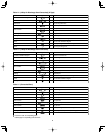
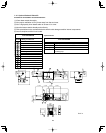
1-7. Straight Equivalent Length of Joints
Design the tubing system by referring to the following table for the straight equivalent length of joints.
Table 1-14 Straight Equivalent Length of Joints
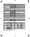
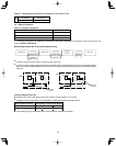
Table 1-15 Refrigerant tubing (Existing tubing can be used.)
Tubing size (in. (mm))
Material O Material 1/2H • H
ø1/4" (ø6.35) t1/32 (t0.8)
ø3/8" (ø9.52) t1/32 (t0.8) ø1-1/8" (ø28.58) t5/128 (t1.0)
ø1/2" (ø12.7) t1/32 (t0.8) ø1-1/4" (ø31.75) t3/64 (t1.1)
ø5/8" (ø15.88) t5/128 (t1.0) ø1-1/2" (ø38.10) over t3/64 (t1.15)
ø3/4" (ø19.05)
over t5/128 (t1.0)
ø1-5/8" (ø41.28) over t3/64 (t1.20)
ø7/8" (ø22.22) t5/128 (t1.0)
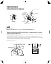
* When bending the tubes, use a bending
radius that is at least 4 times the outer
diameter of the tubes.
In addition, take sufficient care to avoid
crushing or damaging the tubes when
bending them.
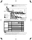
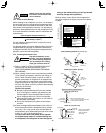
1-8. Additional Refrigerant Charge
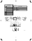
Additional refrigerant charge amount is calculated from the liquid tubing total length as follows.
Required amount of charge = Necessary Amount of
Refrigerant Charge Per Unit (14053 Type) + (Amount
of refrigerant charge per ft. of each size of liquid tube
×
its tube length) + (...) + (...)
* Always charge accurately using a scale for weighing.
ø5/8"
(ø15.88)
ø3/8"
(ø9.52)
ø3/8"
(ø9.52)
ø1/4"
(ø6.35)
ø1/2"
(ø12.70)
ø5/8"
(ø15.88)
ø1/2"
(ø12.70)
Total system horsepower
Suction tubing
Discharge tubing
Indoor unit type
7
912
18 24
36
48
Liquid tubing
Gas tubing
Liquid tubing
0.8
1.3
1
2345
Distribution
joint –
solenoid valve
kit tubing
Solenoid valve
kit – Indoor
unit tubing
connection
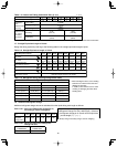
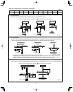
*1: For the solenoid valve kits, use type 160 with parallel specifications. Branch the tubing before and after the solenoid valve kits.
Table 1-13 Indoor Unit Tubing Connection Size ( 1 – 40)
in. (mm)
Gas tubing size (in.(mm))
1/2"
(12.7)
5/8"
(15.88)
3/4"
(19.05)
7/8"
(22.22)
1"
(25.4)
1-1/8"
(28.58)
1-1/4"
(31.8)
1-1/2"
(38.1)
90o elbow
1 ft.
(0.30 m)
1.1 ft.
(0.35 m)
1.4 ft.
(0.42 m)
1.6 ft.
(0.48 m)
1.7 ft.
(0.52 m)
1.9 ft.
(0.57 m)
2.3 ft.
(0.70m)
2.6 ft.
(0.79 m)
45o elbow
0.8 ft.
(0.23 m)
0.9 ft.
(0.26 m)
1 ft.
(0.32 m)
1.2 ft.
(0.36 m)
1.3 ft.
(0.39 m)
1.4 ft.
(0.43 m)
1.7 ft.
(0.53 m)
1.9 ft.
(0.59 m)
U-shape tube bent
(R2–23/64–3–15/16 in.)
3 ft.
(0.90 m)
3.4 ft.
(1.05 m)
4.1 ft.
(1.26 m)
4.7 ft.
(1.44 m)
5.1 ft.
(1.56 m)
5.6 ft.
(1.71 m)
6.9 ft.
(2.10 m)
7.8 ft.
(2.37 m)
T r ap bend
7.5 ft.
(2.30 m)
9.2 ft.
(2.80 m)
10.5 ft.
(3.20 m)
12.5 ft.
(3.80 m)
14.1 ft.
(4.30 m)
15.4 ft.
(4.70 m)
16.4 ft.
(5.00 m)
14.0 ft.
(5.80 m)
Y-branch distr ibution joint Equivalent length con version not needed.
Ball v alve f or ser vice Equivalent length con version not needed.
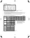
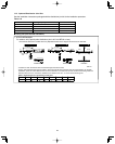
Table 1-16-1 Amount of Refrigerant Charge Per ft.,
According to Liquid Tubing Size
Liquid tubing
size
ø1/4"
(ø6.35)
ø3/8"
(ø9.52)
ø1/2"
(ø12.7)
ø5/8"
(ø15.88)
ø3/4"
(ø19.05)
ø7/8"
(ø22.22)
Amount of
refrigerant
charge (oz/ft.)
0.279 0.602 1.38 1.99 2.78 3.93
Table 1-16-2 Necessary Amount of Refrigerant
Charge Per Unit
CHDZ09053
CHDZR09053
CHDZ14053
CHDZR14053
— 113 oz/unit


