


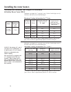
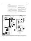
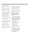
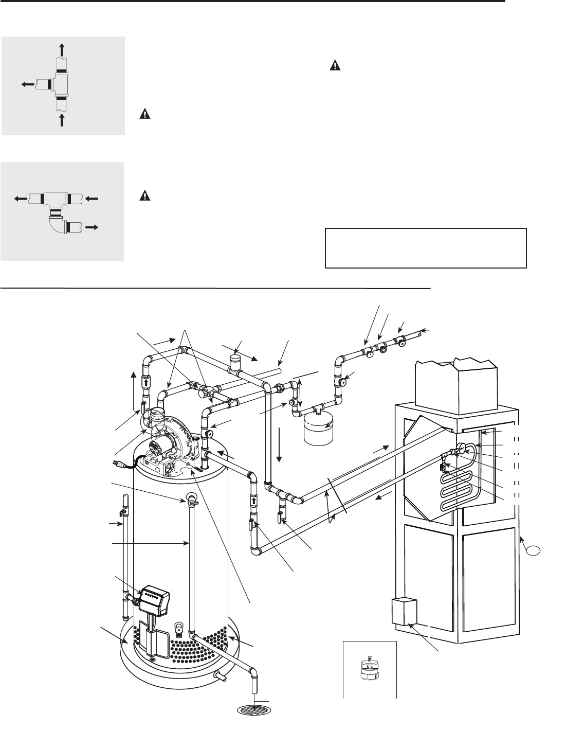
Tee fitting for vertical hot
water supply lines.
Hot water
supply to
house
From HOT
outlet on
water heater
Hot water
supply to
heating
unit
Supplemental instructions for gas water heaters installed
in potable water/space heating applications.
Local codes or plumbing authority requirements may vary from the instructions or diagrams provided
in this manual and take precedent over these instructions.
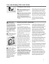
Tee fitting for horizontal hot
water supply lines.
From HOT
outlet on
water heater
Hot water
supply to
house
Hot water supply
to heating unit
Combination Potable Water and Space Heating Application
Tee fitting must be installed as shown.
This ensures that any air in the water lines
will be purged through the domestic water
faucets and showers.
DANGER: When this system
requires water for space heating at
elevated temperatures (above 125°F
[52°C.]), a mixing or tempering valve
must be installed in the hot water
supply line to the house in order to
reduce the scald hazard potential.
DANGER: Any piping or components
used in the installation of this water
heater in a combination potable and
space heating application must be
suitable for use with drinking water.
DANGER: If this water heater is
installed in an application intended to
supply domestic hot water needs and
hot water for space heating purposes,
do not connect the heater to an existing
heating unit or components of a heating
system that have previously been used
with a non drinking water system. Toxic
chemicals such as those used for boiler
treatment may be present and will
contaminate the drinking water supply
causing possible health risks. Never
introduce toxic chemicals, such as those
used for boiler treatment, into this
system.
Notice: 50' - 0" maximum distance from
water heater to fan coil (developed length)
is required for Massachusetts State.
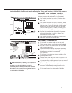
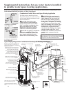
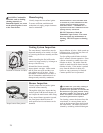
Typical Piping Diagram for Combination Potable/Space Heating Installation
Spring loaded check valve in heating unit
hot water supply line and cold water return
line (not supplied with water heater)
NOTE: This check valve is incorporated
in some heating units. Refer to the
installation instructions supplied with
specific heating unit to determine if it is
required.
All water piping shall be insulated in
accordance with Local and State Energy
Code.
Isolation valve in
cold water return line
from heating unit (not
supplied with water
heater)
Nominal 3/4" size mixing or tempering valve
(refer to warning above). Follow mixing or
tempering valve manufacturer’s instructions for
installation of the valve.
Temperature and pressure relief
valve discharge line
Air Handler
Drain valve
(not supplied with
water heater)
Hot water
to space heater
Temperature and Pressure Relief
Valve, tie to location approved by
local code
See diagrams above for proper
pipe application for vertical
or horizontal supply lines.
Isolation valve in hot water supply line
to heating unit (not supplied with water
heater)
3/4" cold water supply
3/4" Tempered
domestic hot water
supply to house.
Gas line to water heater
6” Air Gap
Combustion Air Inlet
Openings
2 Gallon Thermal
Expansion Tank (if
required-not supplied
with water heater)
Air vent
Heat Trap
6” Min.
3/4" Shut-Off Valve (Typ.)
3/4" Check Valve with 1/8" Hole
Pressure Gauge
3/4" Shut-Off Valve (Typ.)
3/4" Shut-
Off Valve
(Typ.)
Hot water coil
All bronze pump.
Check valve
internal in pump.
Air bleed valve.
Water Sample Tap.
T
FAN
ON
OFF
HEAT
COOL
To HVAC Unit.
Electronically controlled pump timer.
Activates every 6 hours for 60 seconds.
Wire to bronze pump.
3/4" HWS & HWR
to Heating Coil.
Minimum of 2'-0" developed length
of 3/4" pipe.
Water Heater drain pan installed in
accordance with the Local and State
Code
Water Heater to be in accordance with
the Local and State Energy Code
Gas Fired
Water Heater
Gas Direct Vent discharge
must comply with Local
and State Codes
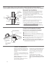
Vacuum Relief Valve
(Not Supplied)
If required, install per local codes
and valve manufacturer’s
instructions.
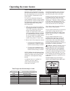
120° to 130°
140°
22
Gas Control (Thermostat)