


12
Installing the water heater.
The water heater must be installed with the factory supplied blower assembly in place.
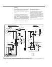
Venting
The water heater must be vented to the
outdoors as described in these instructions.
DO NOT connect this water heater to
an existing vent or chimney - it must
be vented separately from all other
appliances.
NOTICE: This unit can be vented using
only the following recommended pipe
material. Use only 2- or 3-inch diameter
pipe.
PVC (Schedule 40, ASTM D1785)
CPVC (Schedule 40, ASTM F441)
ABS (Schedule 40, ASTM D2661)
ABS (Schedule 40 DWV, Cellular Core,
ASTM F891)
The fittings, other than the TERMINATION,
should be equivalent to the following:
PVC (Schedule 40 DWV, ASTM D2665)
CPVC (Schedule 40, ASTM F438)
ABS (Schedule 40 DWV, ASTM D2661)
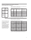
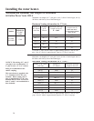
The unit may be vented horizontally
through a wall or vertically through the
roof.
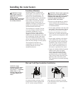
Vent pipe runs must be adequately
supported along both vertical and
horizontal lengths.
Maximum unsupported length is
recommended to be no more than 6 feet.
It is imperative that the first hanger
be located on the horizontal length
immediately adjacent to the first
90-degree elbow from the vertical rise of
vent pipe connected to the water heater.
The support method used should isolate
the vent pipe from floor joists or other
structural members to help prevent the
transmission of noise and vibration.
Do not support, pin or otherwise secure
the venting system in a way that restricts
the normal thermal expansion and
contraction of the chosen venting material.
If the water heater is being installed as a
replacement for an existing power vented
water heater, a thorough inspection of
the existing venting system must be
performed prior to any installation work.
Verify that the correct materials as
detailed above have been used, and
that the minimum or maximum vent
length and terminal locations as
detailed in this manual have been
met.
Carefully inspect the entire venting
system for any signs of cracks or
fractures, particularly at the joints
between elbows or other fittings and
the straight length of vent pipe.
Check the system for signs of sagging
or other stresses in the joints as a
result of misalignment of any
components in the system.
If any of these conditions are found,
they must be corrected in accordance
with the venting instructions in this
manual before completing the
installation and putting the water
heater into service.
DANGER: Failure to
install the blower assembly
and properly vent the water
heater to the outdoors as
outlined in the Venting
section of this manual will
result in unsafe operation of
the water heater causing
bodily injury, explosion,
fire or death.
To avoid the risk of fire,
explosion, or asphyxiation
from carbon monoxide,
NEVER operate the water
heater unless it is properly
vented and has adequate air
supply for proper operation
as outlined in the Venting
section of this manual.
The vent pipe must overlap
a minimum of ½” on each
connection. It is important
that the vent pipe engages
fully into any pipe fitting
and be kept in that position
until the adhesive has fully
cured. DO NOT drill or
punch holes in the plastic
pipe or fittings.
NOTICE: This unit is
equipped with a Flammable
Vapor Sensor. Do not
apply power until enough
time has passed to allow the
vapors from the primer and
cement to dissipate.
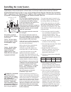
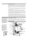
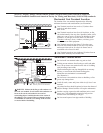
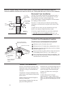
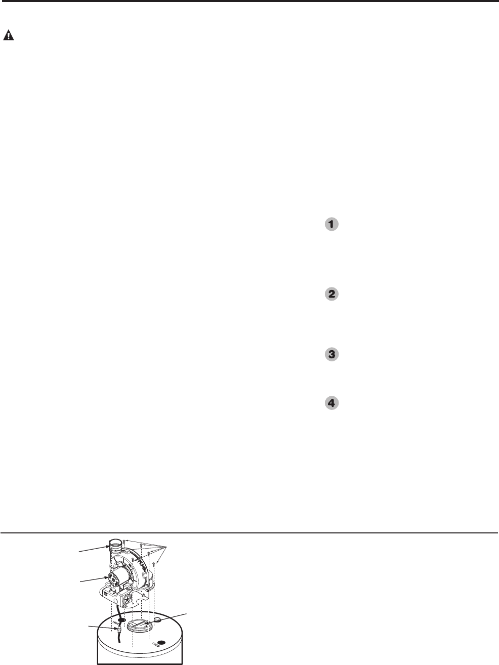
Blower Assembly Installation
(if not factory installed)
Connect blower assembly with the electrical connector. Attach
Blower Assembly to top pan using the six (6) screws provided
(See diagram to the left). Install rubber coupling (supplied in
the box with water heater) on blower housing and secure it.
NOTICE: The Blower Assembly is model specific and only
the blower assembly supplied should be used on this water
heater.
Blower
Assembly
Rubber
Coupling
Sheet Metal
Screws
Electrical
Connector
Flue
Baffle
Additional installation infor-
mation for The Commonwealth
of Massachusetts is located on
the back page of this manual.