


18
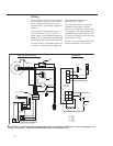
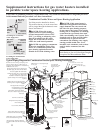
Wiring
If local codes permit, the water heater may
be connected to electric service with the
power cord provided (DO NOT use an
extension cord). A grounding receptacle is
required.
If local codes do not permit the use of
cord connections, a 120 V, 50/60 Hz
power supply, with suitable disconnecting
means, must be connected to the black and
white leads in the heater control enclosure.
A knock-out hole is provided to permit use
of conduit or metal-clad cable connectors.
The maximum current draw is
approximately 5.0 amps.
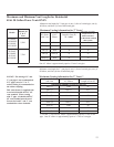
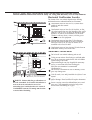
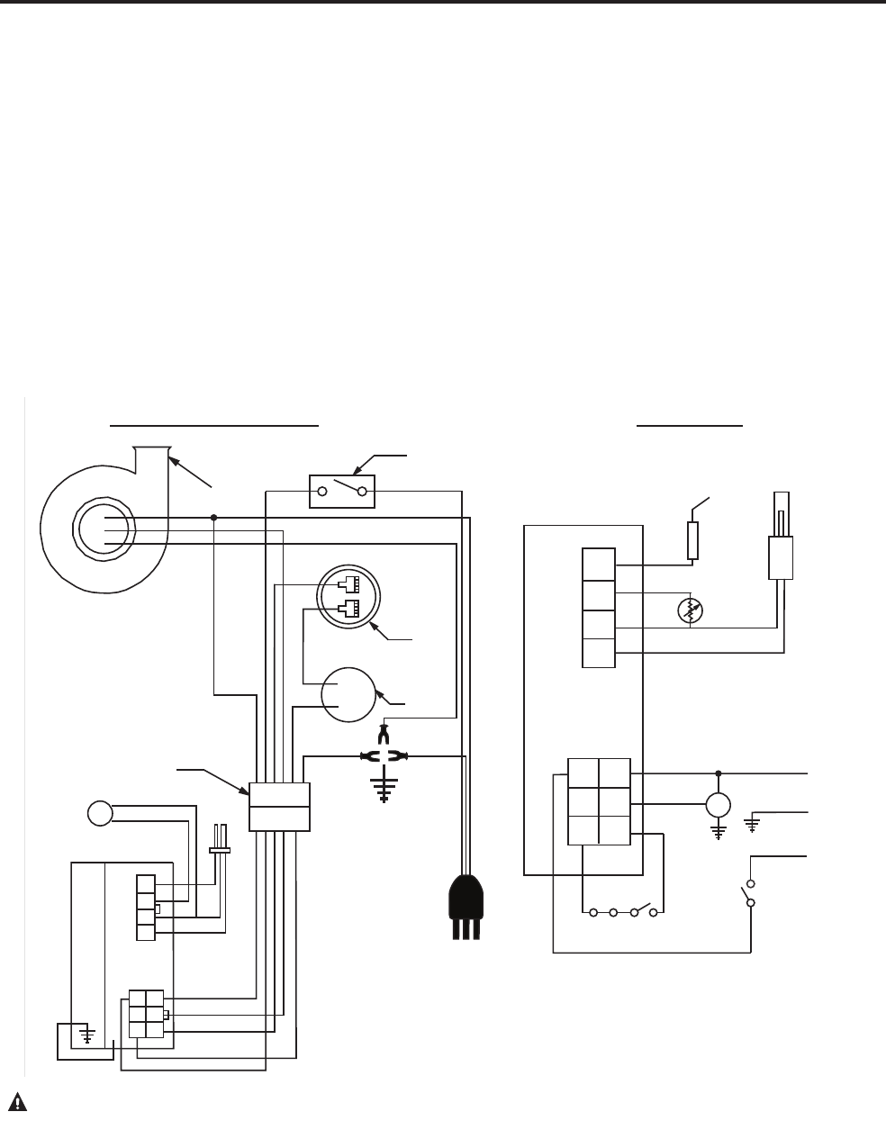
The water heater must be electrically
grounded in accordance with local
codes, or, in the absence of local codes,
in accordance with latest edition of the
National Electric Code ANSI/NFPA No.
70. Refer to the figures below for water
heater internal wiring.
NOTE: It is not recommended that this
unit be installed on a GFCI circuit.
CAUTION! Label all wires prior to disconnection when servicing controls. Wiring errors can cause improper and
dangerous operation. VERIFY PROPER OPERATION AFTER SERVICING!
W
G
G
BK
BK
BK
BK
W
R
Y
R
BL
BL
PIN 5 - BL
PIN 6 - G
PIN 1 - W
PIN 2 - R
PIN 3 - R
PIN 4 - Y
G
SCHEMATIC
CONNECTION DIAGRAM
“H”
“N”
BL
BL
GAS
VALVE
IGNITER AND
FLAME PROBE
ELECTRONIC
CONTROL
ELECTRONIC
CONTROL
FV
INDUCER
6 PIN CONNECTOR
ON / OFF
SWITCH
PRESSURE
SWITCH
TEMPERATURE
SWITCH
BK = BLACK
BL = BLUE
G = GREEN
R = RED
W = WHITE
Y = YELLOW
L2
G
I
L1
SIZE: 6.5” X 5.5”
COLOR: BLACK
APPROVED BY:
Y
W
R
R
FV SENSOR
FLAME
SENSOR
IGNITER
PRESSURE
SWITCH
TEMPERATURE
SWITCH
ON / OFF
SWITCH
W
W
AX4761