


WARNING: Do not attempt to convert this water heater for use with a different type of gas other than the type
shown on the rating plate. Such conversion could result in hazardous operating conditions.
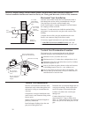
Leak Testing
The water heater and its gas connections
must be leak tested at normal operating
pressures before it is placed in operation.
Turn on the manual gas shut-off
valve near the water heater.
Use a soapy water solution to test for
leaks at all connections and fittings.
Bubbles indicate a gas leak that must
be corrected.
The factory connections to the gas
control (thermostat) should also be leak
tested after the water heater is placed in
operation.
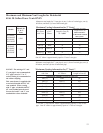
High Altitude
Input rating of this water heater is
based on sea level operation. At higher
elevations the actual input rate may be
lower than the value listed on the rating
label due to the derating of natural gas and
LP gas. This water heater can be installed
at elevation up to 2,000 feet without any
change or modification.
For installation between 2,000 and 7,700
feet, refer to the Venting Information
tables on page 13 and 14 for maximum
vent lengths.
Installations above 7,700 feet are not
authorized.
Contact the local gas supplier for more
information.
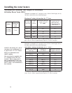
Pressure Testing the Gas Supply System
The water heater and its manual gas
shut-off valve must be disconnected from
the gas supply piping system during any
pressure testing of that system at
pressures in excess of 3/8 psi (10.5” w.c.)
for natural gas, or 1/2 psi (14” w.c.) for
LP gas.
The water heater must be isolated from
the gas piping system by closing the
manual gas shut-off valve during any
pressure testing of the gas supply piping
at pressures equal to or less than
3/8 psi (10.5” w.c.) for natural gas, or
1/2 psi (14” w.c.) for LP gas.
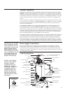
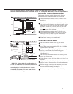
Gas Supply
The branch gas supply line to the water
heater should be clean 1/2” black steel
pipe or other approved gas piping
material.
A ground joint union or ANSI design
certified semi-rigid or flexible gas
appliance connector should be installed
in the gas line close to the water heater.
The National Fuel Gas Code (NFGC)
mandates a manual gas shut-off valve: See
(NFGC) for complete instructions.
If flexible connectors are used, the
maximum length shall not exceed 36”
and must meet the requirements in ANSI
Z21.24-Connectors for Gas Appliances.
If lever type gas shut-offs are used,
they shall be T-Handle type.
Compound used on the threaded joints of
the gas piping must be of the type resistant
to the action of LP gas. Use compound
sparingly on male threads only.
A sediment trap should be installed at the
bottom of the gas line.
Do not use excessive force (over 31.5 ft
lbs.) in tightening the pipe joint at the gas
control (thermostat) inlet, particularly if
teflon pipe compound is used, as the valve
body may be damaged.
The inlet gas pressure to the water heater
must not exceed 10.5” w.c. for natural gas,
or 14” w.c. for LP gas. For purposes of
input adjustment, the minimum inlet gas
pressure (with main burner on) is shown
on the water heater rating plate. If high or
low gas pressures are present, contact your
gas supplier for correction.
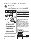
WARNING: Never use
an open flame to test for
gas leaks, as property
damage, personal injury, or
death could result.
WARNING: Failure to
install a water heater
suitable for the altitude at
the location it is intended to
serve, can result in improper
operation of the appliance
resulting in property
damage and/or producing
carbon monoxide gas, which
could result in personal
injury, or death.
11