


17
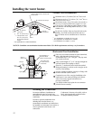
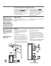
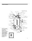
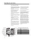
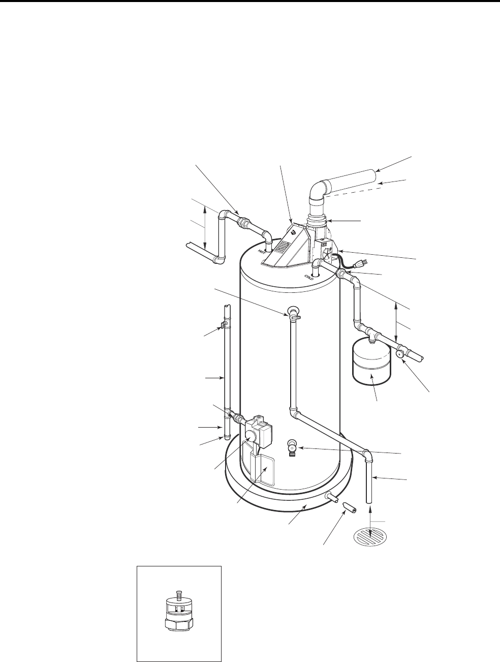
Typical Installation
Heat Trap
6" (15cm) Min.
Heat Trap
6" (15cm)
Min.
Flue Pipe (ABS or PVS)
to Outside Vent Terminal
Rubber Coupling
Blower Assembly
Anode
(located undernea t
h
Blower Assembly)
Union
Union
To Cold
Water Supply
Thermal Expansion
Tank
(If Required)
Shut-off Valve
Air Gap
6" (15cm)
Hot Water
Outlet to
Fixtures
To Gas
Supply
Manual Gas
Shut-off
Sediment Trap
Cap
Drain Pan Pipe
to suitable drain
Auxiliary Catch Pan
Thermostatic
Gas Valve
Jacket Door
Ground Join t Union
Drain Valve
Relief valve discharge
line to suitable open
drain
Temperature & Pressure
Relief Valve
Pitch up 1/4"
per foot
NOTICE: The National
Fuel Gas Code (NFGC) or
CAN/CSA B149,
Installation Code,
mandates a manual gas
shut-off valve: See (NFGC)
or (CAN/CSA B149) for
complete instructions.
Local codes or plumbing
authority requirements
may vary from the
instructions or diagrams
provided and take
precedent over these
instructions.
Vacuum Relief Valve
(Not Supplied)
If required, install per local codes
and valve manufacturer’s
instructions.