


A new combination temperature and pressure relief valve, complying with the Standard for Relief Valves
and Automatic Gas Shut-Off Devices for Hot Water Supply Systems, ANSI Z21.22, is supplied and must
remain in the opening provided and marked for the purpose on the water heater. No valve of any type
should be installed between the relief valve and the tank. Local codes shall govern the installation of
relief valves.
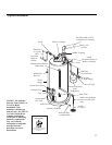
Relief Valve
The pressure rating of the relief valve
must not exceed 150 PSI (1034 kPa), the
maximum working pressure of the water
heater as marked on the rating plate.
The Btuh rating of the relief valve must
equal or exceed the Btuh input of the
water heater as marked on its rating plate.
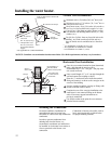
Position the outlet of the relief valve
above a suitable open drain to eliminate
potential water damage. Piping used
should be of a type approved for hot water
distribution.
The discharge line must be no smaller
than the outlet of the valve and must pitch
downward from the valve to allow
complete drainage (by gravity) of the
relief valve and discharge line.
The end of the discharge line should not
be threaded or concealed and should be
protected from freezing. No valve of any
type, restriction, or reducer coupling
should be installed in the discharge line.
13
Thermal Expansion
Determine if a check valve exists in the inlet water line. Check with your local
water utility company. It may have been installed in the cold water line as a separate
back flow preventer, or it may be part of a pressure reducing valve, water meter or water
softener. A check valve located in the cold water inlet line can cause what is referred to
as a “closed water system”. A cold water inlet line with no check valve or back flow
prevention device is referred to as an “open” water system.
As water is heated, it expands in volume and creates an increase in the pressure within
the water system. This action is referred to as “thermal expansion”. In an “open”
water system, expanding water which exceeds the capacity of the water heater flows
back into the city main where the pressure is easily dissipated.
A “closed water system”, however, prevents the expanding water from flowing back
into the main supply line, and the result of “thermal expansion” can create a rapid and
dangerous pressure increase in the water heater and system piping. This rapid pressure
increase can quickly reach the safety setting of the relief valve, causing it to operate
during each heating cycle. Thermal expansion, and the resulting rapid, and repeated
expansion and contraction of components in the water heater and piping system can
cause premature failure of the relief valve, and possibly the heater itself. Replacing the
relief valve will not correct the problem!
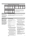
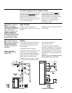
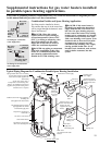
The suggested method of controlling thermal expansion is to install an expansion tank in
the cold water line between the water heater and the check valve. The expansion tank is
designed with an air cushion built in that compresses as the system pressure increases,
thereby relieving the over pressure condition and eliminating the repeated operation of
the relief valve. Other methods of controlling thermal expansion are also available.
Contact your installing contractor, water supplier or plumbing inspector for additional
information regarding this subject.
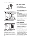
Water Supply Connections
Refer to the illustration on page 17 for suggested typical installation. The installation of
unions or flexible copper connectors is recommended on the hot and cold water
connections so that the water heater may be easily disconnected for servicing if
necessary. The HOT and COLD water connections are clearly marked and are 3/4” NPT
on all models. Install a shut-off valve in the cold water line near the water heater.
NOTICE: Do not apply
heat to the HOT or COLD
water connections. If sweat
connections are used, sweat
tubing to adapter before
fitting adapter to the water
connections on heater. Any
heat applied to the water
supply fittings will
permanently damage the
dip tube and/or heat traps.