


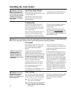
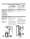
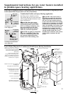
Wiring
If local codes permit, the water heater may
be connected to electric service with the
power cord provided (DO NOT use an
extension cord).
A grounding receptacle is required.
If local codes do not permit the use of cord
connections, a 120 V, 50/60 Hz power
supply, with suitable disconnecting means,
must be connected to the black and white
leads in the heater control enclosure.
A knock-out hole is provided to permit use
of conduit or metal-clad cable connectors.
The maximum current draw is
approximately 5.0 amps.
The water heater must be electrically
grounded in accordance with local codes, or,
in the absence of local codes, in accordance
with latest edition of the National Electric
Code ANSI/NFPA No. 70; or in Canada, the
latest edition of the Canadian Electric Code
CSA C22.1.
NOTICE: It is not recommended that this
unit be installed on a GFCI circuit.
High Altitude
This water heater is certified for
installations at elevations up to 7,700 feet
(2347m).
Installations above 7,700 feet (2347m) are
not permitted.
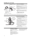
Pressure Testing the Gas Supply System
The water heater and its manual gas shut-
off valve must be disconnected from the
gas supply piping system during any
pressure testing of that system at
pressures in excess of 3/8 psi (10.5” w.c.)
(2.6 kPa) for natural gas, or 1/2 psi (14”
w.c.) (3.5 kPa) for LP gas.
The water heater must be isolated
from
the gas piping system by closing the
manual gas shut-off valve during any
pressure testing of the gas supply piping
at pressures equal to or less than
3/8 psi (10.5” w.c.)(2.625 kPa) for
natural gas, or 1/2 psi (14” w.c.)
(3.5 kPa) for LP gas.
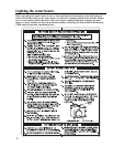
WARNING: Failure to
install a water heater
suitable for the altitude at
the location it is intended to
serve, can result in
improper operation of the
appliance resulting in
property damage and/or,
producing carbon monoxide
gas, which could result in
personal injury, or death.
CAUTION: Label all
wires prior to disconnection
when servicing controls.
Wiring errors can cause
improper and dangerous
operations.
VERIFY PROPER
OPERATION AFTER
SERVICING!
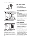
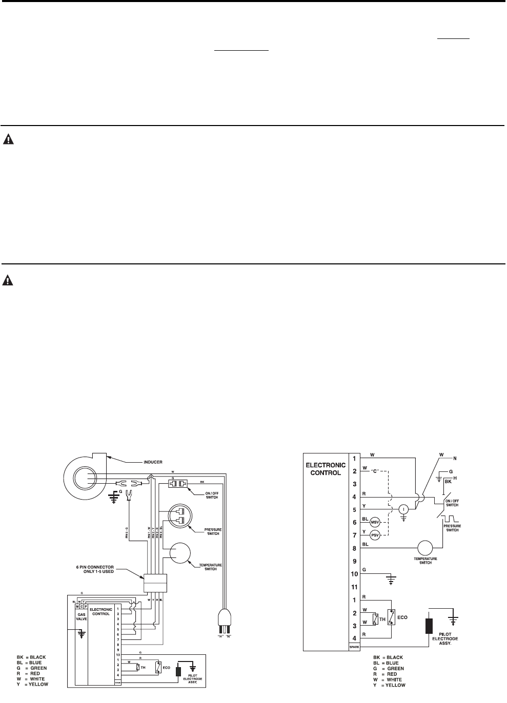
Connection Diagram
Schematic Diagram
15